Custom Overmolded
Cable Assemblies
Cablum designs and manufactures custom overmolded cable assemblies with integrated strain relief, connector protection and environmental sealing options for automotive, industrial, medical equipment and outdoor applications.
Integrated Protection At The Connector Interface
The cable-to-connector junction is often one of the most mechanically vulnerable areas of a cable assembly. Overmolding encapsulates the termination and creates an integrated protective structure around the connector, cable jacket and strain-relief area.
Strain Relief
Helps distribute bending stress across a wider section of the cable and connector interface.
Sealing Options
IP67 or IP68 protection can be designed and validated according to connector geometry, tooling and customer test requirements.
Mechanical Protection
Encapsulation can help protect terminations from vibration, abrasion and handling damage.
Custom Geometry
Molded shapes, logos, colors and ergonomic features can be customized for the application.
Custom Overmolded Interconnect Solutions
Overmolded cable assemblies can be developed around customer-specified connectors, cable types, tooling requirements and environmental conditions.
Circular Connector Cable
Custom overmolded circular connector assemblies for industrial and equipment applications.
- M8 / M12 / M23 options
- Straight or right-angle designs
- Shielded and unshielded versions
Waterproof Power Cable
Sealed power cable assemblies for outdoor, washdown and demanding equipment environments.
- Sealing design options
- Power connector integration
- Custom cable lengths
Sensor Cable Assembly
Overmolded sensor and signal cables for automation, monitoring and control equipment.
- Compact connector designs
- Shielding options
- Flexible cable materials
USB & Data Cable Overmolding
Custom overmolded data cable assemblies for electronics and user-facing equipment.
- Custom strain relief profiles
- Logo and color options
- EMI shielding support
Automotive Connector Overmolding
Overmolded connector and cable assemblies for automotive, EV and transportation equipment.
- Connector protection
- Strain relief design
- Customer-specified materials
Y-Split & Junction Overmolding
Custom molded junctions and cable breakouts for multi-branch harness applications.
- Custom branch geometry
- Integrated strain relief
- Prototype and production tooling
Choose The Right Material For The Application
Overmolding material should be selected according to flexibility, temperature, chemical exposure, UV resistance, sealing requirements and appearance. Cablum can support customer-specified compounds or recommend suitable material options during DFM review.
PVC
Cost-effective option for general cable protection and standard indoor applications.
TPE
Flexible material option for ergonomic strain relief and repeated handling.
TPU
Suitable for applications requiring abrasion resistance and mechanical durability.
Low-Pressure Molding
Material and process options for protecting delicate electronics and internal components.
Material Note: Final material selection depends on cable-jacket compatibility, temperature range, flexibility, chemical exposure and required environmental performance.
Engineering The Mold Before Production
Successful overmolding starts with connector geometry, cable compatibility, material flow, sealing surfaces and strain-relief design.
Drawing Review
Review connector dimensions, cable diameter, bend direction, mounting space and performance requirements.
- Connector geometry
- Cable jacket compatibility
- Required bend direction
Tooling Design
Dedicated tooling is designed according to connector shape, volume, molding material and required appearance.
- Prototype and production tooling
- Straight or right-angle designs
- Logo and texture options
Design Validation
Samples can be checked for dimensions, cable exit angle, sealing surfaces, appearance and assembly fit.
- Prototype review
- Fit and assembly checks
- Customer approval before volume production
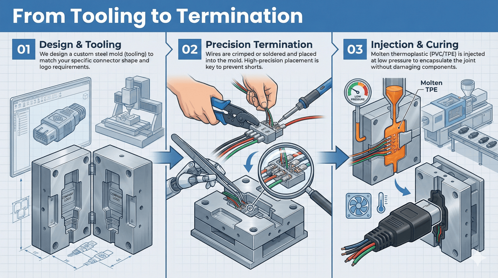
From Tooling To Termination
Design & Tooling
Dedicated tooling is developed based on connector geometry, cable diameter, molding material and production volume.
Cable Preparation
Wires are cut, stripped, crimped or soldered according to the approved assembly process.
Insert Placement
Connectors, terminals and cable components are positioned in the tooling using controlled fixtures.
Controlled Molding
The selected molding material is injected under controlled temperature and pressure to encapsulate the termination.
Inspection & Testing
Finished assemblies are checked for appearance, dimensions, cable alignment and electrical performance.
Primary & Secondary Overmolding Options
Some cable assemblies use a single molding step, while others require multiple molded layers to achieve the required structure and appearance.
Primary Overmolding
The first molded layer can encapsulate internal terminations and create the core mechanical structure.
- Termination encapsulation
- Internal component protection
- Base strain-relief structure
Secondary Overmolding
A second molded layer can add external geometry, branding, grip texture or a different material feel.
- Two-color molding options
- Soft-touch exterior
- Logo and ergonomic features
Controlled Overmolding Production Process
Each project follows approved drawings, tooling parameters and inspection requirements.
01
DFM Review
Review geometry, material, sealing and strain-relief requirements.
02
Tooling
Design, manufacture and validate dedicated molding tools.
03
Termination
Crimping, soldering and connector assembly.
04
Pre-Mold Inspection
Check wire placement, polarity and internal assembly.
05
Overmolding
Molding under controlled temperature and pressure.
06
Finishing
Trim flash, inspect surfaces and verify cable exit geometry.
07
Testing
Electrical, dimensional and mechanical checks.
08
Packing
Lot traceability, protective packing and shipment.
Verification Before Shipment
Finished overmolded cable assemblies are inspected according to approved drawings and project requirements. Additional validation can be arranged where specified.
- Continuity and wiring verification
- Pull-force and strain-relief checks
- Dimensional and visual inspection
- Flex or bend testing where required
- Ingress-protection or environmental testing according to customer requirements
General Overmolding Options
Final material, tooling and validation requirements are selected according to the customer application.
| Item | Available Options |
|---|---|
| Connector Types | Circular connectors, sensor connectors, USB/data connectors, automotive connectors, power connectors and customer-specified components |
| Molding Materials | PVC, TPE, TPU, low-pressure molding materials and customer-specified compounds |
| Tooling | Prototype tooling, production tooling, straight, right-angle, Y-split and custom molded geometry |
| Customization | Logo, color, texture, grip profile, strain-relief geometry and cable exit angle |
| Protection Options | Strain relief, sealing, connector encapsulation, abrasion protection and environmental protection |
| Validation | Continuity testing, pull-force checks, flex testing, dimensional inspection and customer-specified environmental tests |
Where Overmolded Cable Assemblies Are Used
Custom overmolding can be applied to cable assemblies requiring improved strain relief, handling durability, connector protection or environmental sealing.
Robotics & Automation
Overmolded sensor, control and robotic cables for repeated handling and industrial environments.
Automotive & EV
Connector protection and strain-relief solutions for vehicle and electric mobility applications.
Medical Equipment
Ergonomic overmolded cable assemblies for monitoring, diagnostic and user-facing equipment.
Outdoor & Marine
Sealed connector and cable designs for outdoor equipment and moisture-prone environments.
Agricultural Equipment
Rugged cable assemblies for sensors, control systems and field equipment.
Heavy-Duty Equipment
Protected power and signal cable assemblies for construction and transportation equipment.
Consumer Electronics
Custom-molded USB, data, audio and user-interface cable assemblies.
Industrial Machinery
Overmolded power, control and sensor cables for machinery and production equipment.
Explore Related Cable Assembly Capabilities
See Our Cable Overmolding Process
Watch tooling preparation, cable termination, insert placement, molding, inspection and testing.
Overmolded Cable Assembly FAQ
Need A Custom Overmolded Cable Assembly?
Send us your connector drawing, cable specification, sample, BOM or tooling requirements. Our engineering team will review the application and recommend a suitable overmolding solution.