Custom Data & Signal
Cable Assemblies
Cablum manufactures custom data and signal cable assemblies with shielding, twisted-pair, differential-impedance and connector-integration options for industrial automation, machine vision, medical equipment, test systems and custom electronic applications.
Managing Impedance, Shielding & Transmission Performance
Signal attenuation, impedance discontinuity, crosstalk and electromagnetic interference can affect communication reliability. Cable structure, connector selection, shield termination and assembly consistency must be considered together.
Impedance Control
Customer-specified differential impedance options can be supported through suitable cable and connector selection.
EMI / RFI Shielding
Foil, braid and combined shielding options can help reduce interference in electrically noisy environments.
Twisted-Pair Design
Twisted-pair and differential-pair structures can support balanced signal transmission and reduced common-mode interference.
Assembly Consistency
Controlled shield preparation, contact termination and connector assembly help maintain repeatable cable performance.
Custom Cable Assemblies For Electronic Systems
Cable assemblies can be developed around customer-specified interfaces, data protocols, cable constructions, shielding requirements and connector systems.
USB Data Cable Assembly
Custom USB-related cable assemblies for equipment, devices and embedded systems.
- Customer-specified USB interfaces
- Shielding and strain-relief options
- Custom length and connector configuration
Ethernet Cable Assembly
Custom Ethernet-related cable assemblies for machinery, communication equipment and industrial devices.
- Shielded twisted-pair options
- Industrial connector integration
- Customer-specified cable category
LVDS & Display Cable
Differential-pair cable assemblies for displays, cameras and electronic modules.
- 90Ω / 100Ω options where specified
- Compact connector systems
- Shielding and grounding support
Industrial Communication Cable
Custom signal cable assemblies for CAN, RS-485 and industrial communication applications.
- Twisted-pair cable options
- Shielded industrial cable
- M8 / M12 connector options
Machine Vision Cable
Data and signal cable assemblies for cameras, imaging systems and machine-vision equipment.
- Flexible cable options
- Shielded signal structures
- Overmolded connector options
Mixed Data & Power Harness
Custom harness assemblies combining data, signal and power circuits for integrated equipment wiring.
- Power and signal separation
- Shielding and grounding options
- Multi-branch harness integration
Configured Around Signal & Environmental Requirements
Data and signal cable performance depends on conductor geometry, pair construction, insulation materials, shielding, cable length and connector termination. Final construction is selected according to customer specifications and the intended application.
Twisted-Pair Construction
Pair geometry and twist design options for balanced signal and communication circuits.
Foil Shielding
Lightweight shielding option for signal pairs and compact cable structures.
Braided Shielding
Mechanical durability and shielding coverage for demanding equipment applications.
Combined Shielding
Foil and braid combinations can be considered where additional EMI control is required.
Design Note: Shield coverage alone does not determine final performance. Connector construction, grounding method, shield termination and cable length must also be considered.
Custom Termination For Equipment Interfaces
Cablum can integrate customer-specified connectors, contacts, backshells, housings and overmolded interfaces according to the approved BOM and drawing.
USB Interfaces
Customer-specified USB connector types, cable structures and molded strain-relief options.
Ethernet Interfaces
RJ45, industrial Ethernet and customer-specified connector options.
Display Interfaces
LVDS, display and camera-related connector systems according to project requirements.
Industrial Interfaces
M8, M12, D-sub, circular and equipment-specific connector systems.
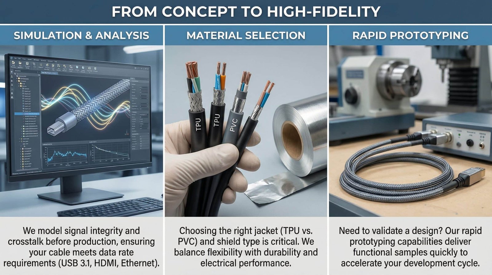
From Interface Requirements To Manufacturable Assembly
Before production, our engineering team reviews the cable construction, connector selection, length, shielding, routing and mechanical requirements. The review helps identify production risks and suitable assembly methods.
Drawing & Specification Review
Review pinout, cable length, connector orientation, shielding and required electrical checks.
Material Selection
Cable jacket, insulation, shielding and connector components are selected according to application requirements.
Shield & Grounding Review
Shield termination, drain-wire routing and grounding points are reviewed against the customer design.
Prototype Support
Engineering samples and pilot builds can support fit, installation and system-level validation.
Controlled Shield Preparation & Connector Assembly
Shield preparation and termination can affect EMI performance and assembly consistency. Processing methods are selected according to cable construction and connector design.
Shield Preparation
Foil, braid and drain-wire structures are prepared according to controlled work instructions.
- Controlled strip dimensions
- Braid combing and folding
- Drain-wire preparation
360° Shield Options
Ferrule, backshell and connector-based shield termination options can be supported where specified.
- Shield ferrule termination
- Metal backshell integration
- Grounding continuity support
Overmolding & Strain Relief
Connector transitions can include heat shrink, molded strain relief or protective backshell options.
- Custom molded geometry
- Cable-exit protection
- Customer-specified materials
Controlled Assembly For Data & Signal Cables
Each project follows approved drawings, pinouts, work instructions and inspection requirements.
01
Engineering Review
Review protocol, pinout, cable construction and connector requirements.
02
Cable Preparation
Cutting, jacket stripping, pair and shield preparation.
03
Contact Termination
Crimping, soldering or IDC termination where specified.
04
Shield Termination
Drain wire, braid, foil and grounding preparation.
05
Connector Assembly
Housing insertion, backshell and locking-component assembly.
06
Strain Relief
Heat shrink, boot, backshell or overmolding options.
07
Electrical Testing
Continuity, shorts, opens and wiring verification.
08
Final Inspection
Dimensions, labels, workmanship and packaging.
Verification Based On Project Requirements
Finished data and signal cable assemblies are electrically verified against approved pinouts. Additional signal or transmission testing can be coordinated according to project needs.
- Continuity and wiring verification
- Short-circuit, open and miswire detection
- Shield continuity and grounding checks
- Contact resistance where required
- Dimensional and connector inspection
- Customer-specified impedance, transmission or third-party validation support
General Data & Signal Cable Options
Final protocol, impedance, connector and test requirements are defined by customer documentation.
| Item | Available Options |
|---|---|
| Cable Types | USB-related, Ethernet-related, LVDS, display, industrial communication, sensor and mixed data/power assemblies |
| Impedance Options | Customer-specified differential impedance, including common 90Ω and 100Ω constructions where suitable |
| Shielding | Foil, braid, combined shielding, drain-wire and 360-degree termination options |
| Connector Systems | USB, RJ45, LVDS/display, M8/M12, D-sub, circular and customer-specified connectors |
| Protection | Backshells, heat shrink, molded strain relief, sleeving and connector protection options |
| Testing | Continuity, short/open/miswire detection, shield continuity, contact resistance and customer-specific transmission validation |
Configured Around Signal & Environmental Requirements
Data and signal cable performance depends on conductor geometry, pair construction, insulation materials, shielding, cable length and connector termination. Final construction is selected according to customer specifications and the intended application.
Twisted-Pair Construction
Pair geometry and twist design options for balanced signal and communication circuits.
Foil Shielding
Lightweight shielding option for signal pairs and compact cable structures.
Braided Shielding
Mechanical durability and shielding coverage for demanding equipment applications.
Combined Shielding
Foil and braid combinations can be considered where additional EMI control is required.
Design Note: Shield coverage alone does not determine final performance. Connector construction, grounding method, shield termination and cable length must also be considered.
Custom Termination For Equipment Interfaces
Cablum can integrate customer-specified connectors, contacts, backshells, housings and overmolded interfaces according to the approved BOM and drawing.
USB Interfaces
Customer-specified USB connector types, cable structures and molded strain-relief options.
Ethernet Interfaces
RJ45, industrial Ethernet and customer-specified connector options.
Display Interfaces
LVDS, display and camera-related connector systems according to project requirements.
Industrial Interfaces
M8, M12, D-sub, circular and equipment-specific connector systems.
From Interface Requirements To Manufacturable Assembly
Before production, our engineering team reviews the cable construction, connector selection, length, shielding, routing and mechanical requirements. The review helps identify production risks and suitable assembly methods.
Drawing & Specification Review
Review pinout, cable length, connector orientation, shielding and required electrical checks.
Material Selection
Cable jacket, insulation, shielding and connector components are selected according to application requirements.
Shield & Grounding Review
Shield termination, drain-wire routing and grounding points are reviewed against the customer design.
Prototype Support
Engineering samples and pilot builds can support fit, installation and system-level validation.
Controlled Shield Preparation & Connector Assembly
Shield preparation and termination can affect EMI performance and assembly consistency. Processing methods are selected according to cable construction and connector design.
Shield Preparation
Foil, braid and drain-wire structures are prepared according to controlled work instructions.
- Controlled strip dimensions
- Braid combing and folding
- Drain-wire preparation
360° Shield Options
Ferrule, backshell and connector-based shield termination options can be supported where specified.
- Shield ferrule termination
- Metal backshell integration
- Grounding continuity support
Overmolding & Strain Relief
Connector transitions can include heat shrink, molded strain relief or protective backshell options.
- Custom molded geometry
- Cable-exit protection
- Customer-specified materials
Controlled Assembly For Data & Signal Cables
Each project follows approved drawings, pinouts, work instructions and inspection requirements.
01
Engineering Review
Review protocol, pinout, cable construction and connector requirements.
02
Cable Preparation
Cutting, jacket stripping, pair and shield preparation.
03
Contact Termination
Crimping, soldering or IDC termination where specified.
04
Shield Termination
Drain wire, braid, foil and grounding preparation.
05
Connector Assembly
Housing insertion, backshell and locking-component assembly.
06
Strain Relief
Heat shrink, boot, backshell or overmolding options.
07
Electrical Testing
Continuity, shorts, opens and wiring verification.
08
Final Inspection
Dimensions, labels, workmanship and packaging.
Verification Based On Project Requirements
Finished data and signal cable assemblies are electrically verified against approved pinouts. Additional signal or transmission testing can be coordinated according to project needs.
- Continuity and wiring verification
- Short-circuit, open and miswire detection
- Shield continuity and grounding checks
- Contact resistance where required
- Dimensional and connector inspection
- Customer-specified impedance, transmission or third-party validation support
General Data & Signal Cable Options
Final protocol, impedance, connector and test requirements are defined by customer documentation.
| Item | Available Options |
|---|---|
| Cable Types | USB-related, Ethernet-related, LVDS, display, industrial communication, sensor and mixed data/power assemblies |
| Impedance Options | Customer-specified differential impedance, including common 90Ω and 100Ω constructions where suitable |
| Shielding | Foil, braid, combined shielding, drain-wire and 360-degree termination options |
| Connector Systems | USB, RJ45, LVDS/display, M8/M12, D-sub, circular and customer-specified connectors |
| Protection | Backshells, heat shrink, molded strain relief, sleeving and connector protection options |
| Testing | Continuity, short/open/miswire detection, shield continuity, contact resistance and customer-specific transmission validation |