RF ENGINEERING · BUYER’S GUIDE
RF Cable Assembly Specifications: What to Include in Your RFQ
A connector name and a cable length are only a starting point. A useful RF cable assembly specification also identifies the cable, impedance, operating frequency range, mechanical references and the performance evidence required for acceptance.
Use this guide to prepare a clear enquiry for a custom coaxial connection. For Cablum’s manufacturing scope, see custom coaxial and RF cable assemblies.
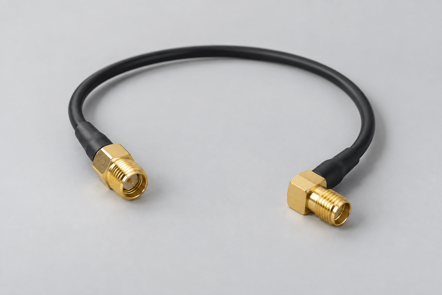
START WITH THE SIGNAL PATH
Specify the Complete Assembly, Not Just the Connector Family
Identify the two equipment interfaces first. Then define the cable and connectors that must connect them. Keep proposed substitutions separate from the approved configuration, so a quotation does not silently change the signal path.
Impedance
State the required nominal system impedance, such as 50 Ω or 75 Ω. Confirm the exact cable and connector variants; a family name alone does not establish the complete assembly specification.
Frequency range
Give the lowest and highest operating frequencies, not only a device’s headline frequency. State where performance limits must apply across that range.
Exact interfaces
List the manufacturer and part number at each end. Include the mating part reference, contact configuration, coupling type and any keying or panel-mount details.
Manufacturer catalogues distinguish cable assemblies by cable type, connector interface, impedance, frequency and length. Check the selected part’s datasheet rather than transferring the rating of another assembly. Reference: Amphenol RF assembly catalogue.
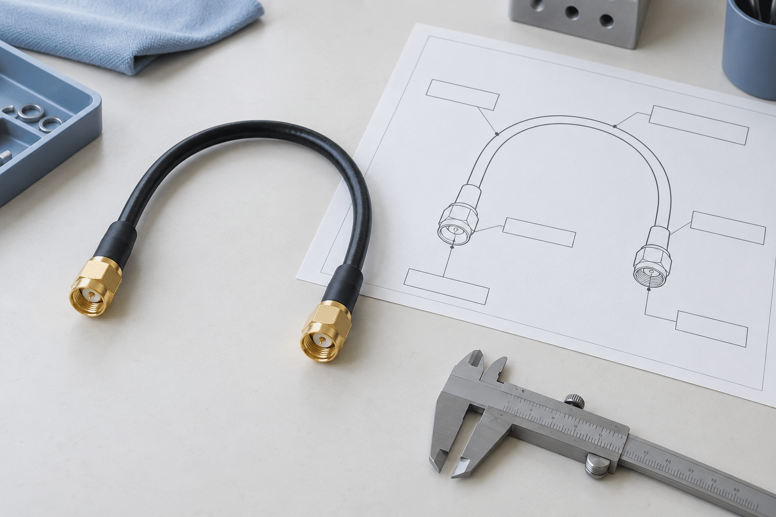
DRAWING DETAILS
Make Length and Connector Orientation Measurable
“300 mm cable” can be interpreted differently if the measurement endpoints are missing. Mark the dimension on the drawing and identify whether it runs between mating reference planes, connector shoulders or another agreed datum.
For angled connectors, show the viewing direction and the required relative orientation. Add panel thickness, mounting hardware and exit clearance where relevant. Keep an installed routing sketch separate from finished assembly dimensions.
Specify the cable manufacturer’s minimum bend requirements for the selected cable and intended use; do not create a universal bend radius from the cable’s appearance.
For the general drawing format, see length and dimension requirements.
ACCEPTANCE CRITERIA
Separate Connection Checks From RF Performance
A connection check answers a different question from an RF measurement. State which checks are required, their limits and whether they apply to every assembly or an agreed sample. Do not treat a generic “tested” statement as a complete acceptance plan.
| Requirement | What the buyer should define | Evidence to agree |
|---|---|---|
| Continuity and unintended shorts | Required conductor connections and prohibited connections, including the intended shield arrangement | Acceptance method and record requirements |
| Insertion loss | Maximum permitted loss at specified frequencies or over a defined frequency range | Measurement setup, agreed limits and results format |
| Return loss or VSWR | The selected metric, its acceptance limit and the applicable frequency range | Measurement reference planes and pass/fail criteria |
| Phase or delay matching, if needed | Matching requirement, reference assembly or group, frequency and tolerance | An explicitly agreed measurement and reporting scope |
| Environmental or mechanical validation, if needed | Specified conditions, method and acceptance criteria | Whether component documentation or assembly-level validation is required |
These are specification fields, not a promise that every test is included or performed in-house. Cablum’s published RF scope separates continuity checks from project-specific RF sampling and externally coordinated specialized RF testing. Confirm the method, coverage, provider, records and cost in your quotation.
Manufacturer RF connector data also separates return loss and insertion loss and notes that values can vary with cable, assembly and workmanship. Reference: Rosenberger MCX technical data. This is a technical reference, not a Cablum product rating or certification.
COPY INTO YOUR ENQUIRY
A Practical RF Cable RFQ Template
Complete the fields you know and label the others “to be confirmed.” Do not fill a missing performance requirement with an assumed value.
Assembly identification: Part number, revision and intended equipment connection.
End A / End B: Manufacturer, exact part number, mating interface and straight or angled configuration.
Cable: Manufacturer, part number, nominal impedance and any mandatory construction or jacket requirements.
Mechanical definition: Finished length, measurement datums, tolerances, connector orientation and routing restrictions.
RF requirements: Operating frequency range; insertion-loss, return-loss or VSWR limits; any phase/delay requirement.
Acceptance plan: Test method, coverage or sample quantity, report format and any external validation.
Commercial scope: Prototype quantity, first production quantity, target timing, packaging and substitution approval rules.
Attach the current drawing and relevant component datasheets. If you are supplying a sample, record what it demonstrates and what still needs written approval. Our drawing vs. sample guide helps resolve conflicting references.
BEFORE APPROVING THE QUOTE
Resolve Three Common Specification Gaps
“Equivalent connector”
Ask for the proposed manufacturer and part number, mating drawing and relevant specification. Record customer approval instead of treating a similar appearance as equivalence.
“Low-loss cable”
Replace this description with a cable reference and measurable assembly acceptance requirements. The quote should state which performance evidence is included.
“Same as the sample”
A sample can show geometry and construction, but does not by itself establish a frequency range or acceptance limit. Record those requirements separately.
Keep RF testing and documentation charges visible when comparing offers. Use the quote breakdown guide to compare the same purchasing scope.
QUICK ANSWERS
RF Cable Specification Questions
Is the connector series enough to obtain an accurate quote?
No. Provide exact connector and cable references, finished dimensions, quantities and the required inspection scope. If a part is undecided, identify it as an open selection item for review.
Does continuity testing prove RF performance?
No. Continuity checks do not establish insertion loss, return loss or VSWR across an operating frequency range. Agree RF acceptance separately when the project requires it.
Can we send a sample before completing the drawing?
A sample can support the review. Include the component information and electrical requirements you have, and identify unresolved details. The approved manufacturing definition should not depend on visual interpretation alone.
Will every assembly receive a full RF test report?
Do not assume this. Agree the applicable test items, sampling or full-quantity coverage, report format and provider before ordering. Specialized testing availability and cost require project-specific confirmation.
Turn Your RF Requirements Into a Reviewable Enquiry
Send the current drawing, cable and connector references, frequency range, order quantity and required acceptance evidence. Cablum will review the assembly and inspection scope before confirming the quotation.