SHIELDED SIGNAL CABLES · DRAWING GUIDE
Shield Termination Requirements for Custom Cable Assemblies
“Use shielded cable” does not define a finished assembly. Your drawing also needs to say what happens to the shield at each end: where it connects, where it remains isolated, how the cable is prepared and what must be inspected.
This guide helps OEM buyers document shield and drain-wire requirements for multicore signal cables. For assembly options, see custom data and signal cable assemblies.
Send Your Shielded Cable Drawing
A documentation guide—not an instruction to change equipment grounding. The system designer must approve the grounding and EMC requirements.
IDENTIFY THE CONSTRUCTION
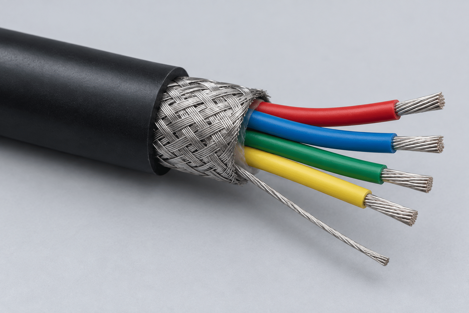
Separate the Shield, Drain Wire and Signal Conductors
Start with the cable manufacturer’s exact part number and construction drawing. Identify any overall shield and any individually shielded pairs separately; do not let one general shield note stand in for several different connections.
Foil shield
A metallic foil layer around the cores or pairs. Record the specified preparation and termination method for the actual cable construction.
Braided shield
A woven conductive layer. Identify the connector accessory or clamp, contact area and preparation detail required by the approved design.
Drain wire
A conductor used in some shield constructions to facilitate termination. Give it its own connection, insulation and length requirements; do not confuse it with a signal core.
Cable constructions vary. Belden’s technical material describes multiple shield types and the use of drain wires with foil shields. Always consult the selected cable’s documentation. Reference: Belden industrial cabling catalogue.
DEFINE BOTH ENDS
Use an End-by-End Shield Connection Schedule
A note such as “shield to ground” leaves the factory to guess the destination and construction. Replace it with a schedule tied to your connector identifiers and drawing details. The fields below are a documentation template, not a recommended grounding scheme.
| Drawing field | End A | End B |
|---|---|---|
| Interface identity | Connector, shell or terminal reference | Connector, shell or terminal reference |
| Shield destination | Exact approved connection point—or explicitly isolated | Exact approved connection point—or explicitly isolated |
| Termination hardware | Manufacturer, part number and detail reference | Manufacturer, part number and detail reference |
| Shield preparation | Jacket cutback, shield contact area and tolerances | Jacket cutback, shield contact area and tolerances |
| Drain-wire treatment | Connection, insulation, cutback or isolation detail | Connection, insulation, cutback or isolation detail |
| Acceptance checks | Intended connections and required isolation | Intended connections and required isolation |
Repeat the schedule for each shield if the cable contains separately shielded pairs or groups. Link it to the conductor map in your pinout table, rather than treating the shield as an undocumented extra wire.
MAKE THE DETAIL BUILDABLE
Specify the Connection Method and Its Boundaries
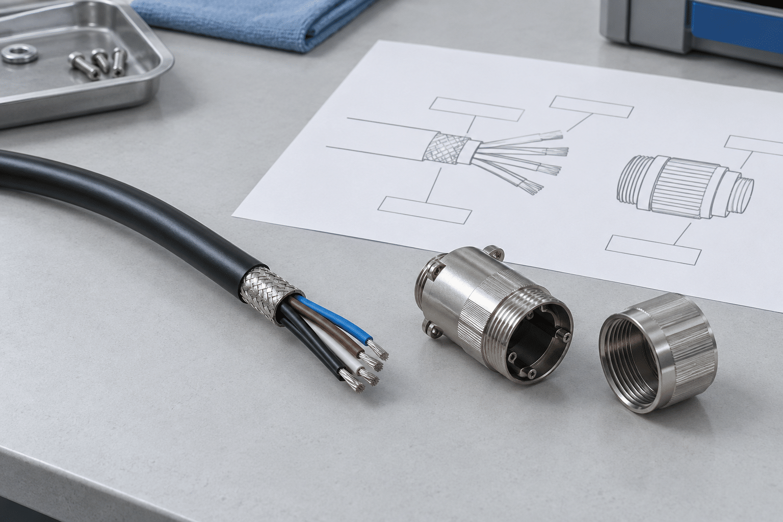
If the design calls for a circumferential shield connection, identify the matching backshell, ferrule or clamp and its assembly instructions. A general “360° shield” note should not leave the hardware and cable preparation undefined.
If the approved design uses a drain-wire connection, define its destination, prepared length, insulation and termination. Do not assume it is electrically interchangeable with a circumferential contact.
Shield connection behavior depends on more than DC resistance. Phoenix Contact’s guidance explains the frequency-dependent effects of the connection path and its geometry. Technical background: shield connections in control cabinets.
Preparation dimensions
Show jacket cutback, the intended shield contact area and relevant insulation boundaries. Reference the selected connector’s preparation drawing.
Isolation boundaries
Identify where shield material or the drain must not contact a shell, core or adjacent terminal. Specify how isolated ends are protected.
Mechanical support
Identify the specified cable support and strain-relief parts separately. Do not assume a shield contact alone provides the required strain relief.
FROM AN AMBIGUOUS NOTE TO A CONTROLLED DETAIL
What to Clarify Before Production
Incomplete note: “Shielded cable; drain to ground.”
Questions to resolve: Which shield? Which end? Which exact destination? What happens at the other end? Which hardware and preparation detail apply? How will the intended connection and isolation be checked?
Controlled documentation: Reference the cable part number, End A and End B schedule, approved termination detail, component list, dimensions and inspection plan. Use the project’s actual approved values—not a generic example copied from another assembly.
For a proposed cable or backshell substitution, review whether the replacement changes the shield construction or contact arrangement. Record the approval before manufacturing. See original vs. alternative components for the purchasing handoff.
INSPECTION SCOPE
Agree What a Finished-Assembly Check Demonstrates
The inspection plan should distinguish assembly conformity from system-level EMC validation. A cable can match an approved connection map without that check proving the complete machine’s immunity or emissions performance.
Visual and dimensional review
Define accessible features, preparation dimensions, hardware, insulation boundaries and records. Specify any checks required before a backshell is closed.
Connection and isolation checks
Identify the exact points to test, intended paths, prohibited connections, method and acceptance limits. Leave no unapproved test settings to inference.
Additional validation
If project-specific EMC or transmission evidence is needed, agree the method, configuration, provider, reporting and cost separately before ordering.
Required tests and records must be confirmed for the project. See test specification requirements; no universal EMC rating or in-house laboratory capability is implied.
COMMON QUESTIONS
Shield and Drain-Wire Documentation FAQ
Should the shield be connected at one end or both ends?
There is no single instruction suitable for every system. The equipment’s approved grounding and EMC design must determine the arrangement. The assembly drawing should record each end explicitly, rather than asking the manufacturer to choose.
Can the drain wire be treated as a spare signal conductor?
No such use should be assumed. Identify its role from the specified cable and approved design, and document its treatment separately from the signal conductors.
Does a continuity pass prove effective shielding?
No. It can establish the specified conductive path under the agreed test conditions; it does not by itself establish shielding effectiveness or system-level EMC compliance.
Can Cablum work from our cable and connector specifications?
Cablum processes custom assemblies to customer-approved drawings and specified components. Send the cable construction, connector and shield hardware, end-by-end details and required checks so manufacturing scope can be reviewed.
Send a Shielded Cable Definition That Can Be Reviewed
Include the cable and connector part numbers, shield schedule for both ends, preparation drawing, required quantity and acceptance plan. Mark unresolved grounding decisions for your system designer’s approval before production.