Custom sleeved cable assemblies
Combined Power & Ethernet Cable Assemblies
Define a power cable and an Ethernet cable as two independent connections, bundled inside one common protective sleeve. The shared covering organizes the requested assembly while each cable keeps its own endpoints and wiring definition.
Cablum makes custom wire harnesses to customer-approved drawings, specified wire and connector requirements. Send your combined-cable layout, component list and test requirements so the proposed assembly scope can be reviewed.
Request a Combined Cable Assembly Review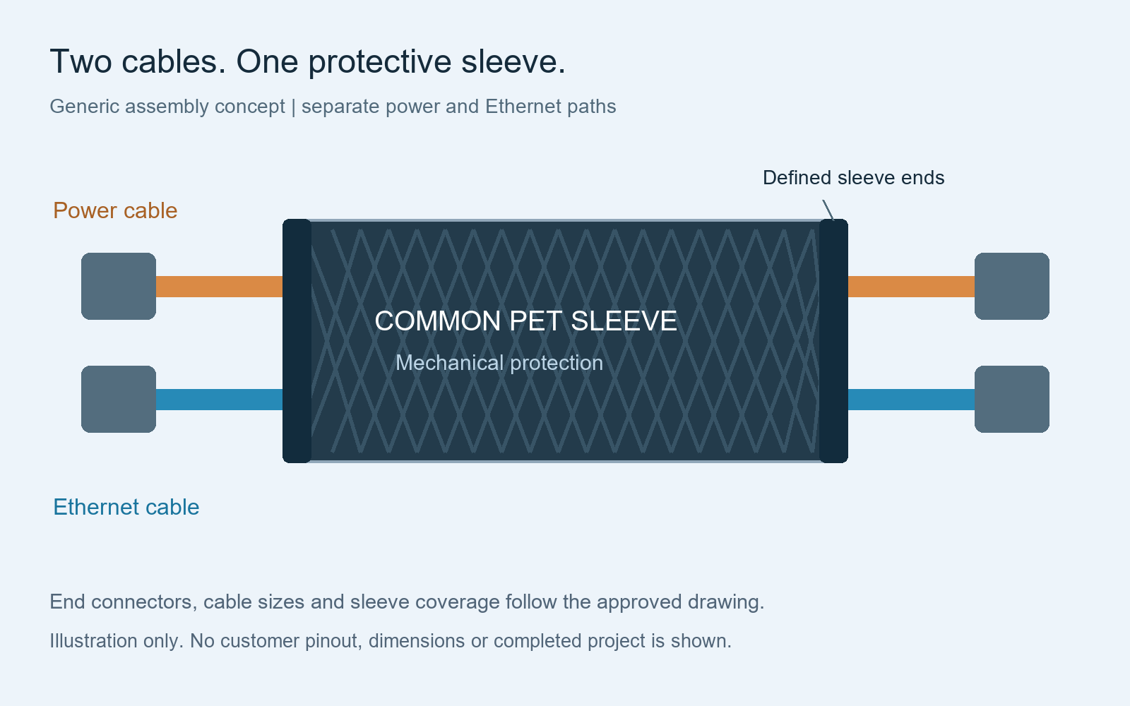
Product configuration
Two separate cables in a common protected bundle
Power connection
Specify both interfaces, the wire construction, circuit identifiers and the approved contact map. Identify unused contacts and any required treatment explicitly.
Ethernet connection
Specify the cable category, conductor construction, connector parts and required wiring scheme. An RJ45-to-RJ45 straight-through lead can be defined with the same approved scheme at both ends.
Common protective sleeve
Specify the sleeve material, finished bundle size, coverage and end treatment. Keep the power and Ethernet cables individually identifiable where they emerge.
This construction groups separate power and network connections. It does not put power onto Ethernet conductors or establish Power over Ethernet compatibility. For broader signal-cable options, see data and signal cable assemblies.
Shared sleeve and separate exits
Define coverage, free lengths and assembly sequence
Measure the sleeve and each cable from named drawing datums. Connector bodies may use different reference faces, so one overall dimension should not be assumed to define both finished cables.
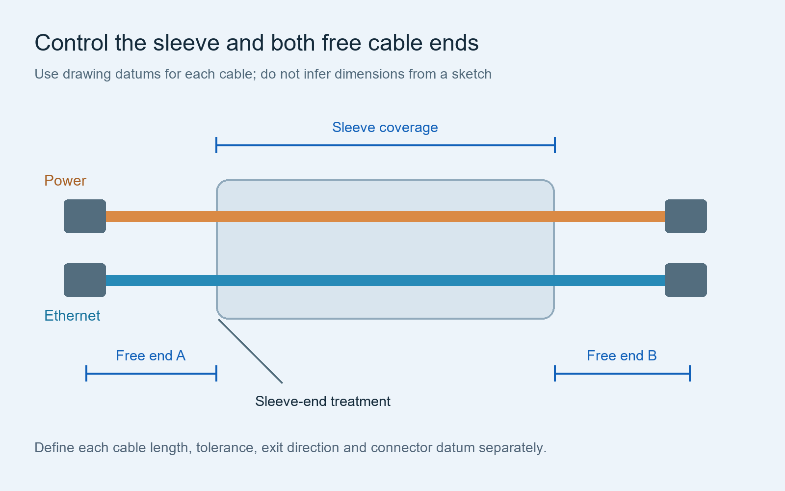
Free cable ends
Dimension the power and Ethernet exits separately where necessary. Include branch direction, connector orientation, tolerances and the space needed to reach each equipment interface.
Sleeve and cuffs
Identify the approved PET sleeve or other specified covering and any heat-shrink cuffs. Define their finished position and coverage; review the dimensions and parts they must pass over.
Strain support
Define cable retention at connectors independently from sleeve-end finish. A neat cuff does not by itself prove that a connector has the required strain relief.
Use the bundling guide for protection details and the dimension guide for measurement references.
Controlled connection definition
Approve both wiring maps before assembly
Give the power connection a pin-to-pin or pin-to-wire table. Identify connector views as mating-face or wire-entry views and use controlled cavity numbers. “Upper-left” is incomplete unless its viewing direction and orientation are also defined.
For the Ethernet path, name the required wiring scheme, such as straight-through T568B at both ends when specified by the customer. Confirm the selected plug is compatible with the cable construction and diameter. State whether a factory-terminated patch cable is to be integrated or terminations are to be assembled for the project.
A generic connector description does not establish mating compatibility. Provide manufacturer part numbers, mating references and the required housing, contact and retention accessories. Proposed equivalents require customer approval.
See the pinout table guide and connector orientation requirements.
Independent verification
Separate electrical wiring checks from Ethernet performance
Power-cable checks
Define intended contact connections, polarity or circuit identifiers, unused contacts and prohibited connections. Agree continuity and short-circuit checks with their acceptance criteria and coverage.
Ethernet-cable checks
Define the required wire-map verification and detection of opens, shorts or miswires. Request any additional network-performance evidence with an explicit method and report requirement.
Finished-bundle checks
Check the shared covering, cable exits, dimensions, labels, connector retention and specified electrical isolation between the separate circuits.
Continuity and wire-map checks do not by themselves establish CAT5e certification or application performance. Required qualification or certification testing must be separately specified and its availability confirmed for the project.
Technical background: Fluke Networks on verification, qualification and certification. See also harness test specification requirements.
RFQ and variants
Quote the complete assembly and each approved option
| RFQ item | What to provide | What to clarify |
|---|---|---|
| Power cable | Wire or cable part, conductor size, operating requirements and connection map | Actual contacts, protection and required verification |
| Ethernet cable | Category, cable and plug references, wiring scheme and length | Factory-terminated cable or project-specific termination; required test evidence |
| Common sleeve | Material reference, bundle fit, coverage, exits and cuffs | Assembly sequence and connector clearance |
| Shielded option | Specified power-cable construction and shield treatment at both ends | Added parts, processing and agreed test scope |
| Connector alternative | Mandatory interfaces and permitted alternative review | Fit, pin numbering, retention and approval before use |
| Order basis | Sample quantity, initial order and repeat-order quantities | Sample scope, production timing, packaging and delivery destination |
A PET protective sleeve is not an electrical shield. If a shielded power-cable option is requested, define its shield construction, connection and isolation requirements separately. A shielded option alone does not prove system-level EMC performance.
See shield termination requirements and component alternative approval. Prices and timing follow review of the actual BOM and assembly requirements.
Installation inputs
Match protection requirements to the equipment environment
State the intended route, supports, bend constraints, connector access and any movement at the cable exits. For mobile equipment, define the actual vibration, abrasion, fluid, temperature and moisture requirements instead of relying on “durable” as an acceptance criterion.
Braided sleeving and heat-shrink finish do not automatically make the assembly waterproof, suitable for continuous flexing or qualified for a machinery environment. Required materials and validation must be specified and agreed for the installation.
Combined power and Ethernet assembly questions
Can separate power and Ethernet cables share a protective sleeve?
This is a custom bundle configuration for project review. Identify the two cable constructions, outside diameters, sleeve fit, routing and acceptance requirements so the complete assembly can be evaluated.
Is this a single hybrid cable or a PoE cable?
The construction described here uses two separate cables under a common covering. A purpose-built hybrid cable and power carried through Ethernet conductors require different definitions.
Does a black PET sleeve provide electrical shielding?
No electrical shielding is specified by the PET sleeve in this construction. Provide a separate shielded cable and its termination requirements if the system design calls for them.
Can the power connector be changed to reduce cost?
A proposed alternative must preserve the approved mating interface, circuit assignment and required retention. Its suitability and any price difference are reviewed before customer approval.
Can a sample be approved before repeat production?
Include the requested sample quantity and review criteria in the RFQ. Agree the assembly drawing, components, dimensions and required records before the production release.
Drawing-based manufacturing
Send both cable definitions and the common-sleeve layout
Provide the component list, separate connection maps, dimensions, protection requirements, quantities and required tests. Cablum reviews the available project information before confirming the assembly and quotation scope.
Send Your Combined Cable RequirementsDrawing checklist · Internal industrial assemblies · Flexible power cable assemblies