Wire harness connector selection guide
2.50 mm vs 2.54 mm Connectors for Wire Harnesses
2.50 mm and 2.54 mm are different contact pitches. A wire harness connector described only by its spacing or a seller’s short name is not sufficiently defined for production. Confirm the manufacturer’s series, housing, contacts and mating part before ordering an assembly.
This guide helps equipment buyers distinguish JST XH from a 2.54 mm header socket, measure pitch correctly and prepare a controlled connector specification for a custom wire harness quotation.
Send Your Connector Requirements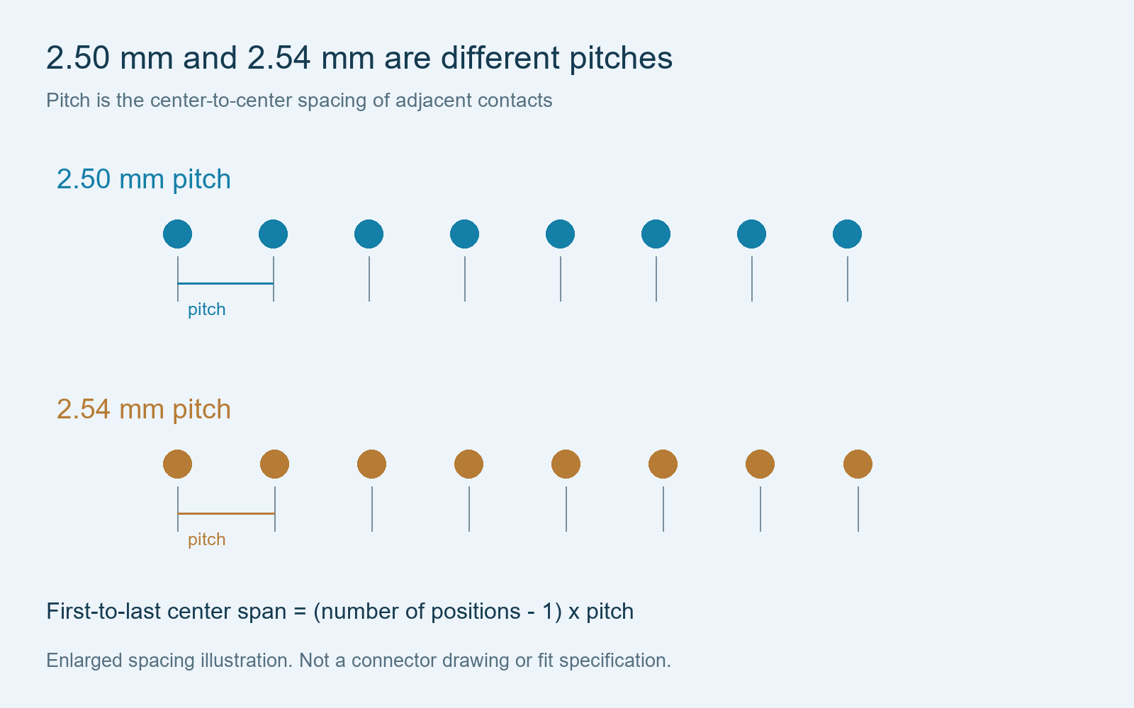
Direct answer
Is JST XH 2.50 mm or 2.54 mm?
JST’s official XH documentation identifies the series as 2.5 mm pitch. Treat a listing labelled “XH2.54” as a reason to request the actual manufacturer and part drawing, not as confirmation that it is an original JST XH component.
A 2.54 mm female header housing is a separate specification. For example, Harwin M20-1060200 is a single-row, two-position female cable housing with 2.54 mm contact pitch. These examples identify two different connector systems; they are not an approved substitution pair.
Manufacturer references: JST XH datasheet and Harwin M20-1060200 product information.
Compare the specification
Pitch is one dimension, not a complete connector identity
| Identification item | JST XH example | 2.54 mm header socket example |
|---|---|---|
| Pitch | 2.50 mm in the JST XH specification | 2.54 mm for the referenced Harwin M20 housing |
| What to specify | Exact XH housing, compatible contact and mating header references | Exact socket housing, compatible contact and mating header references |
| What the spacing does not establish | Wire range, complete mating geometry or approved alternatives | Wire range, complete mating geometry or approved alternatives |
| Assembly definition | Connection map, wire, dimensions and orientation | Connection map, wire, dimensions and orientation |
Check position count, number of rows, pin shape, housing profile, keying, retention and contact engagement against the mating component drawing. Connectors with the same pitch can still belong to incompatible systems.
Names such as “DuPont-style” can help describe an appearance, but the production BOM should use an exact component reference or a controlled, customer-approved alternative.
Measurement
How to measure connector pitch
Pitch is measured between adjacent contact centers, not across the outside of the plastic housing. For a row with several equally spaced positions, measure the first-to-last contact center span and divide by the number of intervals.
Pitch = first-to-last center span / (position count – 1). For ten positions, the nominal span is 22.50 mm at 2.50 mm pitch and 22.86 mm at 2.54 mm pitch. These are calculated spacing examples, not acceptance tolerances for a finished connector.
The difference between adjacent pitches is only 0.04 mm, so a rough photograph or one short measurement may not identify the system reliably. Use measurements to narrow the identification and confirm the result against the manufacturer’s drawing. Do not force a connector onto a header to test compatibility.
When supplying photographs, include a clear mating-face view, side view, any markings and the equipment-side header. A scale reference can assist identification but does not replace a part number.
Parts and assembly
Match the housing, crimp contact and mating header
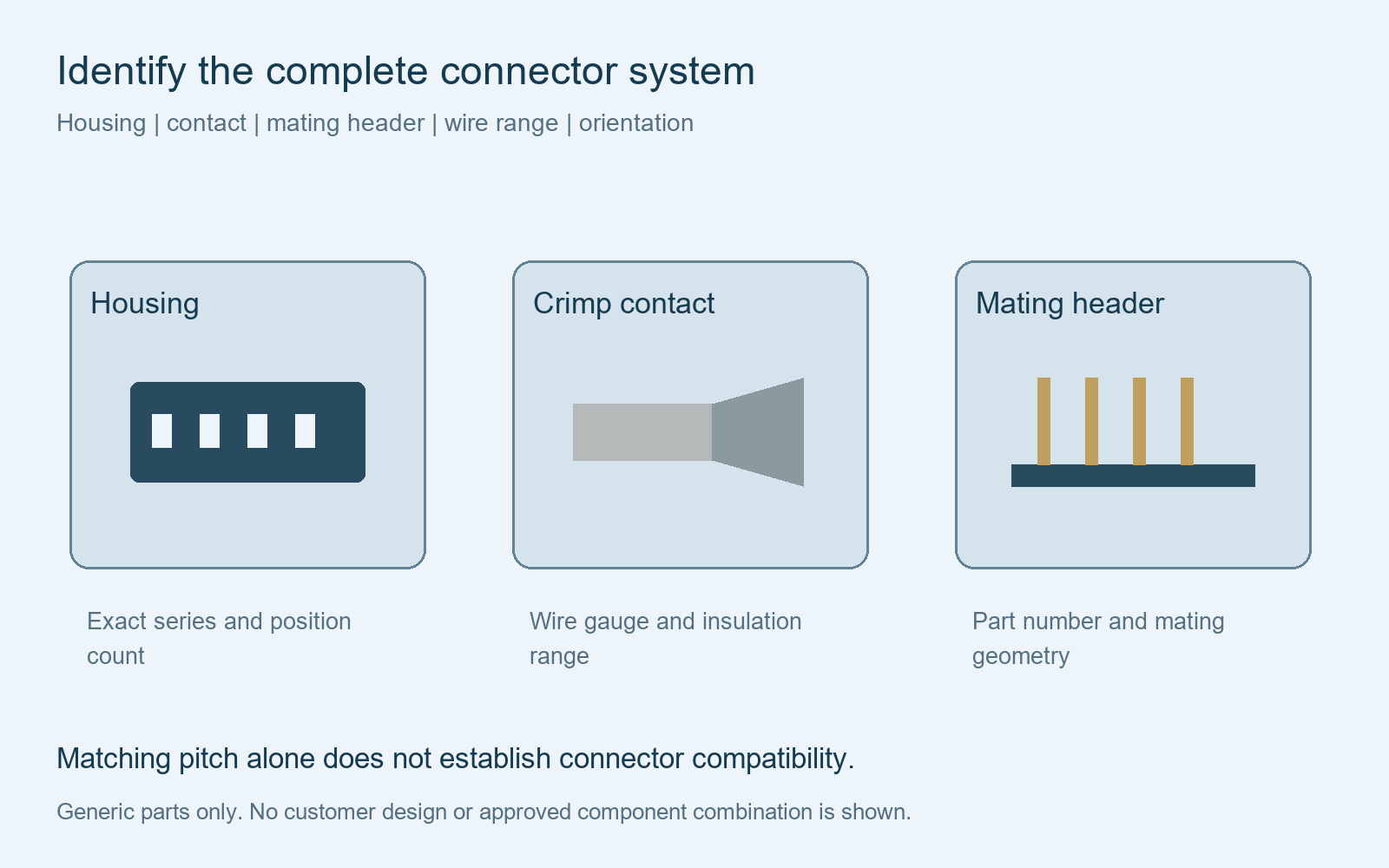
Specify the metal contact separately from the plastic housing where the connector system uses separate crimp contacts. Check the contact’s approved wire gauge and insulation dimensions, then use the manufacturer’s application requirements to define termination and inspection.
A housing that fits the board header does not by itself establish that the proposed contact fits the wire. Likewise, a terminal suitable for the wire is not automatically compatible with another manufacturer’s housing.
For a custom harness, identify each endpoint independently. One assembly can use a 2.50 mm connector at one end and a 2.54 mm connector at the other if those are the interfaces required by the approved equipment design. The wire connection table defines how the two endpoints connect.
RFQ checklist
What to send before a connector-based harness is quoted
Component identity
Manufacturer, series, housing and contact part numbers, position count, mating header and permitted alternatives.
Wiring definition
Wire specification, gauge, color, contact assignments, unused positions and the named viewing direction.
Finished assembly
Lengths, tolerances, branches, protection, labels, quantities and acceptance requirements.
If component identification is incomplete, provide the equipment model, interface drawing or a sample reference for review. Confirm the chosen components and orientation before production rather than leaving a generic connector name in the released BOM.
Cablum manufactures custom wire harnesses to customer-approved drawings and specified wires and connectors. Component availability, tooling, processing and inspection scope are reviewed before quotation.
Related resources: connector selection requirements, BOM requirements, connector orientation and custom pigtail harness assemblies.
Common questions
2.50 mm and 2.54 mm connector questions
Can I replace a 2.50 mm connector with a 2.54 mm connector?
Do not approve a replacement from pitch alone. Confirm the complete mating geometry, contacts, retention, electrical requirements and manufacturer references with the equipment designer.
Does a two-pin connector name tell me which terminal to buy?
No. Two positions describe the circuit count. The housing series and its compatible contact reference, including the wire range, are still required.
Is “XH2.54” enough information for a production BOM?
No. JST documents its XH series as 2.5 mm pitch. Request the actual manufacturer and part references for any ambiguously labelled component.
Can a connector photo confirm the exact brand?
A clear photo can help identify a likely family, but it may not establish the brand, contact plating or exact part variant. Confirm those details using markings, documentation or an approved sample.
Move from identification to assembly
Send a defined connector specification for harness review
Share your BOM, mating interface information, wire requirements and connection drawing. Cablum reviews the custom assembly requirements before confirming the quotation and sample scope.
Request a Custom Harness Review