Endpoint and polarity references
Assign a unique reference to each end. Where applicable, state positive, negative or another approved circuit designation explicitly. Do not leave the connection identity to cable colour or an unlabelled photograph.
Custom cable assemblies · Battery power connections
Cablum makes custom wire harnesses and cable assemblies according to customer drawings, wire requirements and connector requirements. For a proposed battery power connection, send the approved connection layout and component specification for review before manufacturing scope is confirmed.
This page focuses on battery power connection details: end identification, polarity references, terminal orientation and installation protection. It is not a catalogue of pre-rated battery leads or a battery-system design service.
Define the circuit function
A battery power cable request should identify the intended power connection between the specified battery, module or equipment interfaces. A BMS sensing harness request concerns measurement or monitoring connections and needs its own circuit mapping.
Do not describe both simply as “battery wiring.” Label the circuit function in the drawing and separate the power connection requirements from sensing or communication requirements.
These descriptions clarify the request; they do not confirm acceptance of a particular battery design. For broader application context, see Energy Solutions.
Battery connection definition
Assign a unique reference to each end. Where applicable, state positive, negative or another approved circuit designation explicitly. Do not leave the connection identity to cable colour or an unlabelled photograph.
Provide the specified terminal or connector part number and the mating interface reference. For a proposed bolted terminal, include the customer-approved hole and interface dimensions rather than asking the manufacturer to infer fit.
Show the required facing direction and relative orientation of the ends. Identify the drawing view so a mirrored or rotated interpretation is not mistaken for the intended assembly.
Identify the approved wire or cable specification, conductor size and required markings. Operating requirements and component choices must be reviewed together; this page does not provide a universal size-to-current table.
Mark the required covering boundaries and any specified terminal protection. Identify areas that must remain accessible for installation without treating an illustration as an approved protection design.
Specify label text, position and reading direction where required. Keep the finished lead identification consistent with the endpoint references in the controlled drawing.
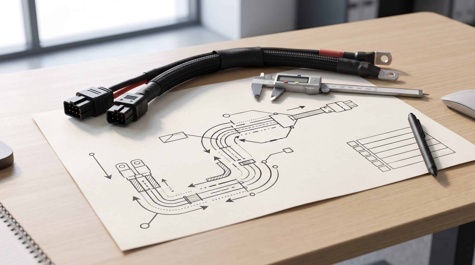
Installation fit
The requested cable shape must be explained relative to the equipment. These are design inputs for review, not installation instructions for an energised battery.
Use the dimension guide to document measurement points. Installation procedures, isolation and system protection remain subject to the equipment design and approved instructions.
Customer-defined operating conditions
The following information supports project review. It is not a statement of Cablum product ratings, test capacity or system-design approval.
| Input | What the customer should define | What must not be assumed |
|---|---|---|
| Voltage requirement | Applicable operating and maximum design conditions, together with the approved component specification. | A voltage rating cannot be assigned from cable appearance. |
| Current and duty | Required continuous load and any applicable peak duration or duty profile. | A conductor size alone does not define a universal assembled-product current rating. |
| Thermal and installation conditions | Specified ambient conditions and relevant enclosure, routing or grouping constraints. | A material temperature rating is not a promise of complete assembly performance. |
| Environment and exposure | Required moisture, contamination, vibration or other conditions relevant to the design. | Terminal coverings do not automatically establish an IP rating. |
| Verification and records | Customer-approved inspection items, acceptance limits and any required reports. | A general continuity check does not establish all electrical or environmental performance. |
Unresolved values should be marked as open questions. Required checks must be agreed for the project; see Quality Testing. For high-voltage application context, see High-Voltage Harnesses.
FAQ
A photograph can explain the intended arrangement, but it does not establish approved polarity references, part numbers, dimensions or operating requirements. Send the drawing and component specification for review.
Not automatically. Identify the power lead and sensing harness separately, with their own connection maps and requirements. Each proposed assembly needs scope confirmation.
Terminal size alone is not a complete design specification. Supply the required operating conditions and approved cable and terminal requirements; unresolved selections must be reviewed rather than assumed.
No. This page concerns drawing-based custom assemblies. It does not establish a stock design, installation procedure, universal rating or approval for every battery system.
Start with the technical definition
Share the drawing revision, BOM, connection ends, cable requirements, quantity and open questions. Cablum will review the requested assembly before confirming manufacturing scope.