INDUSTRIAL EQUIPMENT · INTERNAL CONNECTIONS
Custom Industrial Cable Assemblies for Internal Equipment Connections
Cablum manufactures connector-to-connector and connector-to-terminal-block cable assemblies for control cabinets and industrial equipment. We cut, terminate and assemble the specified wires and connectors to your approved drawing.
Order a finished connection with defined ends, lengths and wire identification—not an unspecified roll of industrial cable. Each configuration is reviewed against your component and installation requirements.
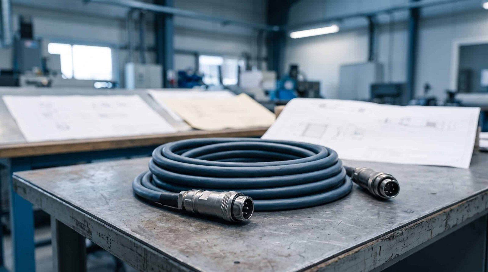
TWO CONNECTION TYPES
Choose the Construction That Matches Your Equipment
Connector-to-Connector Assemblies
For internal connections where both endpoints mate with defined equipment interfaces. Specify the housing and contact references at each end, cavity assignments, connector orientation and finished length.
The two ends do not have to use the same connector. The drawing must identify both interfaces and how each conductor connects between them.
Connector-to-Terminal-Block Assemblies
For connections between a connector interface and a terminal block inside the equipment or control cabinet. One end is assembled into the specified connector; the other is prepared to suit the named terminal block.
Define whether each terminal-block end requires a ferrule, another specified terminal or a stripped conductor. Include the end-preparation dimensions and wire labels; the termination must match the actual terminal-block requirements.
Define Both Ends of the Finished Cable
| Product detail | Connector-to-connector | Connector-to-terminal-block |
|---|---|---|
| Interface | Housing, contact and mating references for both ends. | Connector references plus terminal-block manufacturer and part number. |
| Connection map | Connector A cavity to connector B cavity for every conductor. | Connector cavity to terminal designation, with a matching wire label. |
| End preparation | Specified contacts, accessories and connector exit direction. | Specified ferrule or terminal, or strip length where a bare conductor is required. |
| Dimensions | Finished length between stated datums and any orientation requirement. | Main cable length, jacket breakout and individual lead lengths to reach the terminal positions. |
| Identification | Assembly reference and any required end or conductor markings. | Assembly reference, terminal destination and label location on each prepared lead. |
Use a pinout table for the connection map and a BOM for the approved component list.
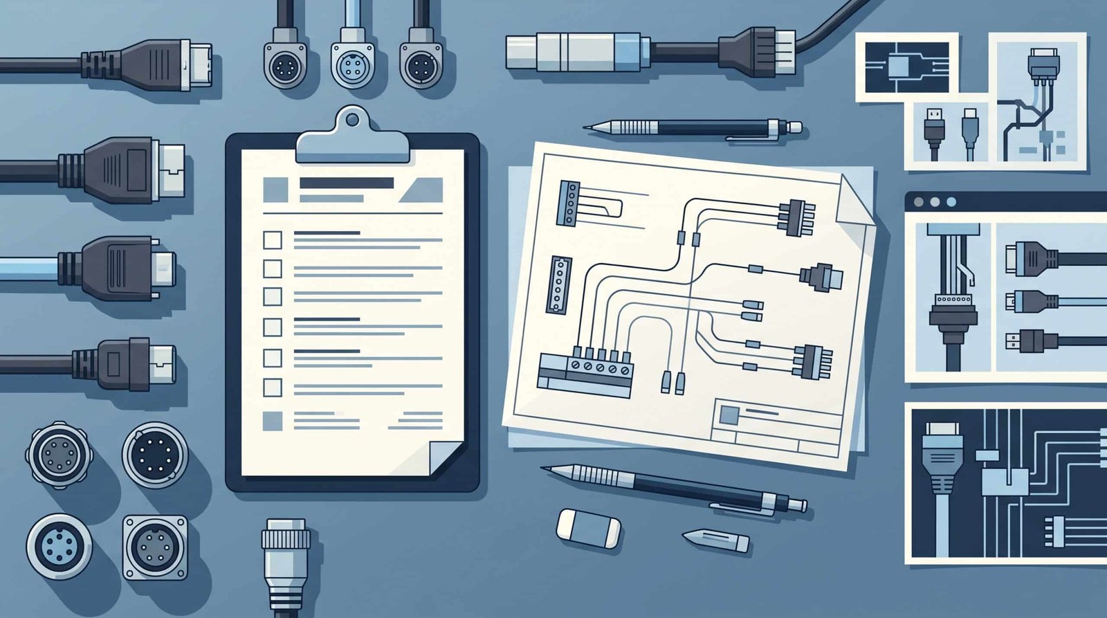
CABINET AND EQUIPMENT FIT
Match the Cable to the Available Installation Space
Show where the cable enters the connector, where the jacket ends and where individual conductors separate toward the terminal block. Give each lead enough defined reach for its intended terminal position rather than assuming every lead has the same length.
Mark sleeve boundaries, heat-shrink locations, label positions and customer-specified strain-relief parts. Include connector access and removal space in the equipment layout supplied for review.
What the Quoted Assembly Includes
For equipment with separate power and Ethernet interfaces that share one cable route, review combined power and Ethernet cable assemblies. Each cable retains its own connector, length and connection definition inside the common sleeve.
The agreed build can cover wire cutting and preparation, specified terminations, connector assembly, identification and protective parts shown on the drawing. The quotation should identify the component sourcing basis and any required samples or setup work.
Inspection requirements are agreed with the order: for example, connection mapping, finished dimensions, terminal retention, labeling and the specified electrical checks. Acceptance limits and required records belong in the approved project documents.
This page covers cable assemblies—not complete control-panel design, cabinet wiring installation or manufacture of bulk cable. Continuous-motion, high-voltage, sealing or special environmental performance is not implied by an internal industrial connection.
Internal Industrial Cable Assembly Questions
Have you made both connection types?
Yes. Cablum has manufactured connector-to-connector and connector-to-terminal-block assemblies for control cabinets or industrial equipment. The particular component combination and build requirements still need review for each order.
Can you use the wires and connectors in our drawing?
Yes. Our custom assembly work follows customer-specified wire and connector requirements. Identify mandatory manufacturer part numbers and whether components will be customer-supplied or sourced for the order. Any proposed alternative requires approval.
Does every terminal-block end use a ferrule?
No. End preparation follows the specified terminal-block interface and approved drawing. Do not assume that one ferrule, terminal or strip length suits every terminal block.
Can the prepared leads have different lengths?
Provide a dimension for each lead or defined group, measured from the stated breakout datum. This allows the requested layout and manufacturing scope to be reviewed before quotation.
Where should I look for moving-machine or broader manufacturing requirements?
See Industrial Automation Wire Harnesses for application requirements, or Cable Harness Assembly Services for the broader manufacturing workflow.
Send Your Internal Connection Drawing
Include both endpoint definitions, specified wire and connector parts, connection map, dimensions and quantity. For terminal-block connections, add terminal designations and the required preparation for each lead.