Custom industrial feedback connections
Custom Servo Motor & Encoder Cable Assemblies
Cablum manufactures custom cable assemblies to customer-approved drawings, specified cables and connectors. For a servo motor feedback cable or encoder cable assembly, send the motor and drive references, complete wiring diagram and mechanical requirements for engineering review.
Legacy equipment replacement projects start with a controlled specification and first-article validation. A matching connector outline or an old cable reference alone does not establish electrical or mechanical compatibility.
Request a Servo Cable Review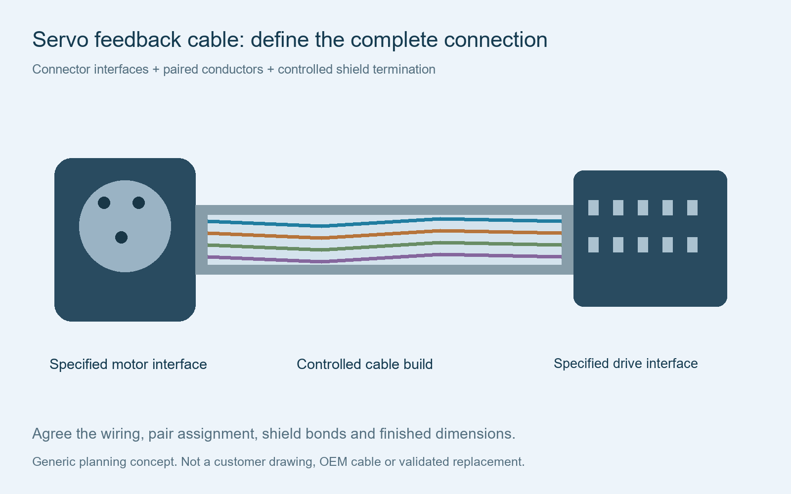
Application-specific assemblies
Define the feedback cable your equipment actually requires
Encoder and feedback connections
Identify the feedback device, signal names, supply requirements and pair assignments. Similar connectors can carry different signals or use different contact numbering.
Motor-to-drive cable layouts
Specify both endpoint references, backshells, cable exits and available installation space. Treat feedback, motor power and brake circuits as separate requirements unless the approved design combines them.
Legacy replacement evaluation
Use the installed assembly reference to locate the correct documentation and revision. Resolve missing details before quoting a replacement as compatible.
This page focuses on feedback interfaces, shield termination and replacement validation. For broader equipment interconnections, see custom industrial cable assemblies.
Drawing-based sampling
Can a prototype be reviewed without an original sample?
A physical sample is not always the starting requirement. Engineering can review a project from complete, consistent documentation: connector ordering codes, mating references, cable construction, a connection table, shield details, finished dimensions and acceptance criteria. The review determines whether that information is sufficient to release a sample build.
Provide clear connector views and contact numbering. Identify mating-face versus wire-entry views, unused contacts, twisted pairs, drain wires, shell connections and any internal links. Include document revisions and resolve conflicting diagrams before production.
If keying, cable entry, installed clearance or undocumented wiring cannot be confirmed, a sample, detailed measurements or equipment-side inspection may still be needed. See our connector orientation guide and pinout table guide.
Cable and screening specification
Specify pairs, shielding and jacket as a complete cable construction
| Requirement | Information needed for review |
|---|---|
| Conductors and pairs | Pair count, conductor size and stranding, insulation, color code and pair assignment |
| Signal properties | Required impedance, capacitance or other controlled characteristics from the equipment specification |
| Shield construction | Individual or overall shields, foil construction, braid coverage and drain wire requirements |
| Jacket and environment | Approved jacket material, diameter, temperature, oil exposure and installation conditions |
| Motion and routing | Fixed or moving use, required bend radius, travel and any defined cycle validation |
| Dimensions | Finished length, reference faces, tolerances, cable exits and branch positions |
A jacket material or shield coverage percentage by itself does not establish suitability for continuous flexing or a particular feedback system. Any proposed cable alternative needs comparison against the full controlled specification.
Equipment-specific instructions govern installation. For an example of an OEM documentation library that separates power, feedback and continuous-flex cable instructions, see Rockwell Automation cable technical documentation. This reference does not establish compatibility with a particular legacy cable.
Shield termination and connector selection
Control the shell, shield and strain-relief arrangement
Show the approved shield termination at each endpoint, including the backshell, clamp, drain-wire destination and any separate chassis bond. Follow the applicable equipment grounding scheme rather than assuming a universal connection at one or both ends.
Specify the connector insert arrangement, contact gender, keying, coupling, plating, termination method and cable-entry range. Include contacts, seals and backshell accessories in the BOM; the connector body reference may not identify the complete assembly kit.
Where cost alternatives are requested, quote the specified original-brand component and a proposed alternative separately. A proposed compatible connector requires documented comparison and approval of mating fit, contact retention, processing requirements and electrical characteristics. A cross-reference is not a validation result. See original versus alternative components.
First-article acceptance
Agree electrical checks and equipment validation before release
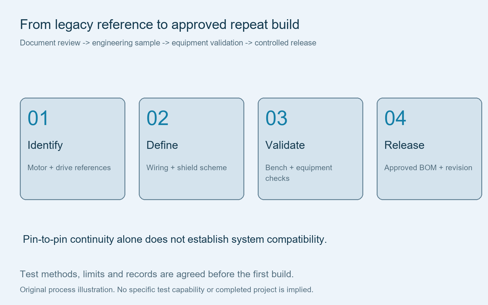
List the checks and records required in the RFQ. Request per-assembly coverage where needed, and agree the test method, fixture, limits and reporting format before a production commitment.
| Requested check | Acceptance plan should define |
|---|---|
| Continuity and pin-to-pin wiring | Controlled netlist, all intended paths, unused positions and resistance limits |
| Shorts and opens | Required isolation between circuits and the treatment of intentional shield or shell links |
| Insulation resistance | Test voltage, duration, limits and permitted circuit groupings for the selected assembly |
| Shield bonding | Bond endpoints, measurement method and resistance limits |
| Visual and dimensional checks | Connector orientation, termination, strain relief, finished lengths and identification |
| Test documentation | Required traceability, measured values, pass/fail records and report format |
These are review inputs, not a claim that every listed test is available for every project. Do not select an insulation or dielectric test voltage solely from a cable jacket marking. Confirm suitability for all fitted components.
Bench electrical checks do not prove operation with the motor, encoder and drive. Customer equipment validation should confirm feedback operation, installation fit and the relevant operating conditions before an independent replacement is approved. See test specification requirements.
Quotation and repeat supply
Separate prototype costs from the approved production build
Send sample and production quantities, destination, packaging requirements and the requested original-brand or alternative-component basis. Material purchasing minimums, component availability, tooling, fixtures and inspection requirements affect the quotation and lead time.
Ask for one-time engineering or tooling charges separately from unit prices. Finished weight and packing dimensions are estimated after the BOM and packaging plan are defined, then checked against the approved first article. No fixed price, sample lead time or minimum order is implied here.
After approval, control the drawing revision, cable and connector references, shield workmanship, inspection plan and approved substitutions. Proposed changes need review before repeat production; an obsolete part should not be silently replaced.
Does a legacy cable number guarantee a ready-made replacement?
No. It is an identification input. Wiring, interfaces, cable properties and equipment validation must be resolved before compatibility can be confirmed.
Can original-brand and alternative connectors be quoted separately?
Request both options. Availability and the technical approval basis are reviewed for the exact components; alternatives require approval before use.
Are test reports and small engineering batches available?
Send the quantities and report requirements for review. Testing scope, records, material purchasing and build feasibility are confirmed in the project quotation.
Build to an approved drawing
Send your servo or encoder cable requirements
Provide the motor and drive references, connector BOM, wiring and shield diagram, cable specification, dimensions and quantities. Cablum will review the assembly requirements before confirming the manufacturing scope, component options, inspection plan, price and lead time.
Send Your Servo Cable RFQIndependent custom assembly review. No OEM endorsement, authorization or validated interchangeability is implied.