As EV platforms, battery systems, energy storage products, and automotive electronics handle higher current and more compact routing, the quality of each wire splice becomes more important. A splice with unstable resistance, weak mechanical strength, or poor process control can create heat, voltage drop, intermittent contact, or long-term reliability issues.
For many standard wire harnesses, crimping remains a proven and practical method. However, for selected high-current or compact splice applications, ultrasonic wire welding can provide a strong solid-state metal-to-metal connection without solder, filler metal, or a separate splice terminal.
This guide focuses on how ultrasonic welding is used in EV battery harnesses, high-current cable assemblies, power distribution wiring, and other applications where electrical stability, space saving, and vibration resistance matter.
Table of Contents
- 1. Why EV Harness Splicing Requires Better Process Control
- 2. What Is Ultrasonic Wire Welding?
- 3. Where Ultrasonic Welding Is Used in EV Cable Assemblies
- 4. Ultrasonic Welding vs Crimping vs Soldering for EV Harnesses
- 5. Key Design Factors Before Choosing Ultrasonic Welding
- 6. Quality Validation for Ultrasonic Wire Welds
- 7. How Cablum Supports EV Harness Splicing Projects
- 8. FAQ
1. Why EV Harness Splicing Requires Better Process Control
EV battery harnesses and high-current cable assemblies often operate under higher electrical, thermal, and mechanical stress than standard signal wiring. The splice area may need to carry high current, fit into limited packaging space, resist vibration, and remain stable over long service life.
Because heat generation is related to electrical resistance, even small changes in splice quality can matter in high-current circuits. A stable splice design must consider conductor material, cross-sectional area, current load, vibration, insulation protection, routing, and inspection requirements together.
Current Load
High-current circuits require low and stable contact resistance to help reduce heat generation.
Vibration and Movement
Automotive and battery systems may experience vibration, shock, and repeated thermal cycling.
Packaging Space
Compact splice geometry can help reduce harness bulk in tight EV battery or power distribution layouts.
Process Traceability
Higher-risk applications often require defined validation, sampling, and inspection documentation.
2. What Is Ultrasonic Wire Welding?
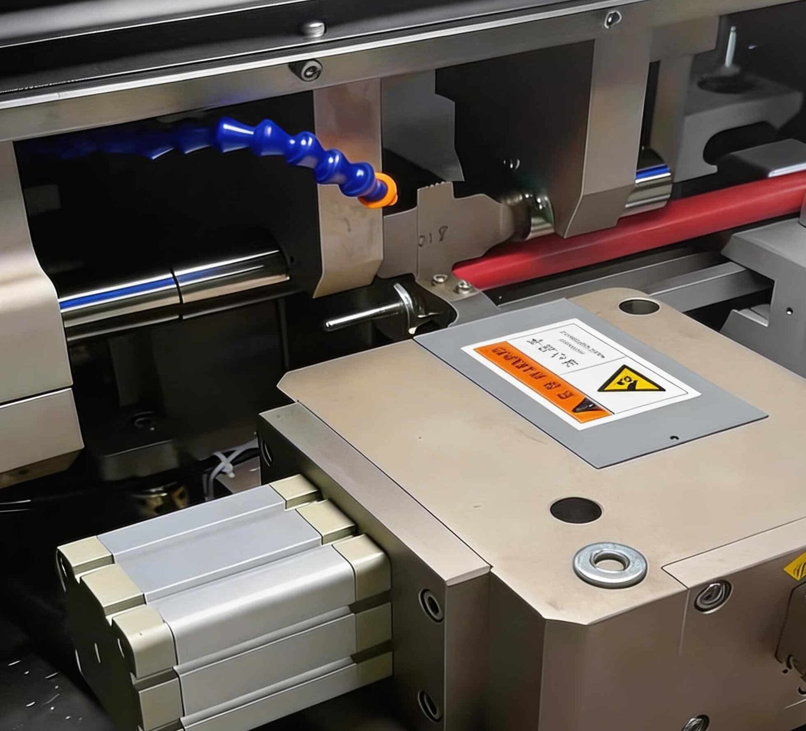
Ultrasonic wire welding is a solid-state joining process. The process uses high-frequency mechanical vibration and pressure to create a metal-to-metal bond between wire strands. Unlike soldering, it does not rely on filler metal or melting the base conductor.
During the process, stripped wires are placed between a sonotrode and an anvil. Under pressure, high-frequency vibration helps disrupt surface oxides and contaminants, allowing clean metal surfaces to bond together. When properly controlled, the result is a compact welded splice with low and stable electrical resistance.
Solid-State Joining, Not Soldering
Ultrasonic welding does not use solder or external filler material. The goal is to form a controlled solid-state metal-to-metal connection while limiting heat exposure to surrounding insulation and components.
3. Where Ultrasonic Welding Is Used in EV Cable Assemblies
Ultrasonic welding is not required for every EV or automotive harness. It is most useful when the splice must combine electrical stability, compact size, high mechanical strength, and repeatable production quality.
EV Battery Harnesses
Used where battery wiring requires stable current paths, compact branch splices, and process validation.
Power Distribution Cables
Useful for joining multiple conductors or creating compact power distribution splice points.
Grounding and Bonding Wires
Can support strong mechanical and electrical connections for grounding paths when properly validated.
Selected Copper-Aluminum Joints
Can support selected dissimilar-metal joining applications, such as copper-to-aluminum, when material, design, and process parameters are properly validated.
4. Ultrasonic Welding vs Crimping vs Soldering for EV Harnesses
Crimping, soldering, and ultrasonic welding each have different strengths. The right choice depends on the wire size, current rating, reliability target, process control, inspection plan, and customer drawing.
| Method | Best Used For | Strengths | Design Considerations |
|---|---|---|---|
| Ultrasonic Wire Welding | High-current splices, compact branch points, EV and industrial power wiring. | Compact splice, low and stable resistance, no separate splice terminal. | Requires process setup, compatible wire materials, validation, and proper inspection. |
| Crimping | Standard terminals, signal wiring, low-to-medium current assemblies, many production harnesses. | Flexible, widely used, cost-effective, strong when properly controlled. | Requires correct terminal, applicator, crimp height, pull force, and inspection. |
| Soldering | Selected low-volume, repair, or electronics-related applications. | Useful in some specific electrical joining cases. | May introduce stiffness, heat exposure, flux residue, or vibration fatigue risk if misapplied. |
| Mechanical Splice Terminal | General wire joining where approved splice terminals are specified. | Simple process, compatible with many standard harness designs. | May add size, weight, and resistance depending on terminal and process quality. |
Related Reading
For a broader comparison, read our Ultrasonic Welding vs Crimping for Wire Harness Splicing guide.
5. Key Design Factors Before Choosing Ultrasonic Welding
Ultrasonic welding should be reviewed as part of the complete cable assembly design. Wire material, cross-sectional area, insulation protection, splice location, testing requirements, and production volume all affect whether it is the right method.
| Design Factor | What to Review | Why It Matters |
|---|---|---|
| Wire Size and Strand Count | Cross-sectional area, strand construction, and bundle geometry. | Affects weld energy, compression, splice size, and mechanical performance. |
| Wire Material | Copper, tinned copper, aluminum, or selected dissimilar-metal combinations. | Material affects weldability, oxidation, long-term stability, and validation needs. |
| Current Rating | Operating current, peak current, voltage drop, and thermal concerns. | High-current splices require stable resistance and thermal review. |
| Splice Location | Routing area, bend radius, branch position, and nearby components. | Determines protection, strain relief, and packaging constraints. |
| Insulation Protection | Heat shrink, tape, sleeve, tubing, or molded protection. | Protects the welded area from short circuit, abrasion, moisture, and handling damage. |
| Testing Requirement | Pull force, resistance, visual, dimensional, cross-section, or thermal testing. | Defines how the welded splice will be validated before production release. |
| Production Volume | Prototype, pilot run, high-mix production, or mass production. | Affects process setup, fixture design, sampling plan, and unit cost. |
6. Quality Validation for Ultrasonic Wire Welds
For high-current EV harnesses, welding quality should be validated through a defined inspection and testing plan. The exact plan depends on the customer standard, application risk, wire size, production volume, and drawing requirements.
| Validation Method | What It Checks | When It Is Useful |
|---|---|---|
| Visual Inspection | Weld appearance, wire placement, insulation condition, and obvious defects. | Routine process and final inspection. |
| Weld Dimension Check | Weld width, height, length, and geometry when specified. | Process setup and dimensional consistency. |
| Pull Force Testing | Mechanical strength of the welded splice. | Sample validation, FAI, process approval, and quality checks. |
| Resistance Measurement | Electrical resistance across the welded connection. | High-current or low-resistance applications. |
| Cross-Section Analysis | Internal weld structure, strand bonding, compression, and possible defects. | Destructive validation when required by project or customer specification. |
| Thermal Review | Heat generation under operating current or test load. | EV battery, power distribution, and high-current cable applications. |
Quality Note
Cross-section analysis is a destructive inspection method and is normally used for sample validation, process setup, quality investigation, or customer-specific requirements. It is not usually performed on every weld.
7. How Cablum Supports EV Harness Splicing Projects
Cablum supports OEM customers with custom wire harness and cable assembly manufacturing, including drawing review, BOM review, splice method evaluation, prototype builds, process planning, material sourcing, and quality inspection support.
For EV battery harnesses and high-current cable assemblies, our team can help review whether ultrasonic welding, crimping, mechanical splicing, or another joining method is most suitable based on the application and project requirements.
DFM Review
Review wire size, material, splice location, current rating, routing, and protection method.
Prototype Support
Build engineering samples for fit, function, process review, and design verification.
Splice Protection Planning
Review heat shrink, tape, sleeve, tubing, routing, and strain relief around the splice area.
Inspection Plan Support
Define visual inspection, pull force testing, resistance checks, and cross-section analysis when required.
If you are developing an EV battery harness, power distribution cable, or high-current custom wire harness, send us your drawing, BOM, wire material, current rating, target quantity, and testing requirements. Early review can help reduce redesign, sourcing risk, and production uncertainty.
Need Ultrasonic Wire Welding Review for an EV Harness?
Cablum can help evaluate wire size, splice method, current rating, insulation protection, testing requirements, and production feasibility for EV battery harnesses and high-current cable assemblies.