Customer-specified equipment connections
Custom D-Sub Cable Assemblies
Cablum manufactures custom cable assemblies and wire harnesses to customer-approved drawings, specified wires and connector requirements. For a D-sub cable project, send the exact connector parts, contact map, opposite endpoints and finished dimensions for review.
Define the complete assembly, including the backshell, fastening hardware, cable exit and required protection. Component sourcing, termination method, sample requirements and quotation scope are confirmed against your project information.
Request a D-Sub Cable Assembly Quote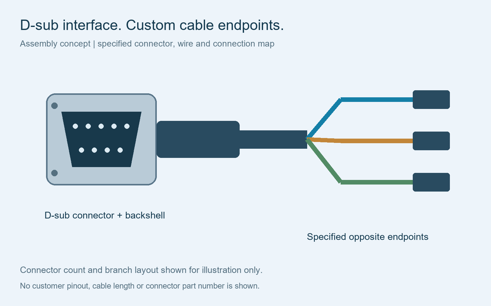
Finished assembly formats
D-sub connector to the endpoints your equipment requires
A custom D-sub assembly does not have to use the same connector at both ends. Identify every endpoint and the corresponding circuit rather than assuming a standard straight-through cable.
D-sub to another connector
Provide both manufacturer part numbers, contact genders and the pin-to-pin map. Specify any separate power, signal or shield connections.
D-sub to individual leads
Define each lead’s length, identifier and termination: a specified terminal, ferrule, prepared wire end or another approved treatment.
D-sub to multiple branches
Identify the branch positions and destinations. State whether the branches share a jacket or require sleeves and local protection.
For other connector-to-wire formats, see custom pigtail wire harness assemblies. Projects with several measurement endpoints can also refer to custom test equipment harnesses.
Connector identification
Specify the exact D-sub part, not only DB9, DB15 or DB25
Common labels such as DB9, DB15 and DB25 are useful search terms, but the RFQ should include the manufacturer’s full part number and drawing. Confirm the contact count, row arrangement, density, plug or receptacle type and cable termination style.
The label “15-pin D-sub” alone is insufficient to define the connector. Show the actual contact layout and mating reference so the assembly uses the intended interface.
Manufacturer documentation distinguishes connector variants and termination options. TE Connectivity’s D-sub connector overview is one reference for these distinctions; it is not a list of parts automatically available from Cablum.
If a supplied sample is the starting point, provide the matching equipment connector information and confirm any permitted component alternatives. Substitutions require approval before use.
Mechanical definition
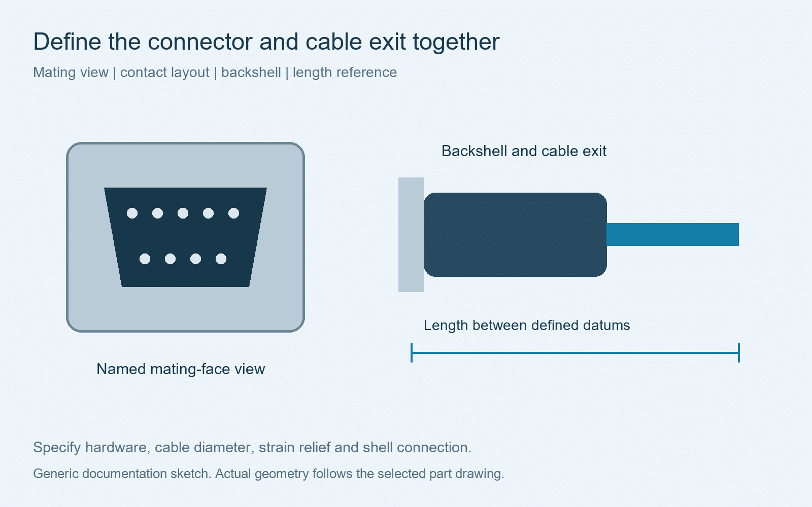
Include the backshell, fasteners and cable exit
Backshell and hardware
List the approved hood or backshell and fastening hardware. Identify fitted items and any accessories supplied loose.
Cable exit and support
Show the required exit direction, cable diameter and available clearance. Specify the intended cable clamp or strain-relief arrangement.
Length and branches
Name the reference faces used to measure length. Add tolerances, branch positions and free-lead dimensions where relevant.
Use the selected component’s installation instructions to define its fit. For dimensions outside the connector, refer to the harness length and dimension guide.
Electrical definition
Control contact mapping and shield connections
Provide a connection table with the D-sub contact number, opposite endpoint, conductor identifier and circuit function. Mark the drawing as a mating-face or wire-entry view and show an orientation reference. Identify contacts that remain unconnected.
Specify wire gauge, insulation and cable construction. A connector’s contact count does not establish the permitted voltage or current for the completed assembly; provide the operating requirements and selected component ratings for project review.
For shielded cable, define whether and how the shield or drain wire connects to the shell, backshell, another contact or an equipment ground. Do not leave shield treatment to an assumed standard pinout.
See pinout table requirements, connector orientation requirements and shield termination assemblies for the supporting documentation.
Quotation package
What to send for a custom D-sub cable quotation
| RFQ input | Information required |
|---|---|
| Connector set | Part numbers, mating references, contacts, backshell and fastening hardware |
| Cable and wire | Conductor count, gauge, insulation, jacket, shield and specified material references |
| Controlled drawing | Pin map, connector views, length datums, tolerances, branches and labels |
| Acceptance requirements | Visual and dimensional checks, electrical checks, limits and required records |
| Commercial basis | Sample and order quantities, approved alternatives, packaging and delivery destination |
Define continuity and short-circuit verification for the required circuits, plus shield connections where applicable. Any additional electrical or mechanical test needs its own method and acceptance criteria. The agreed test scope forms part of the quotation.
Where fit needs approval, identify the mating connector, fixture or equipment reference used for the sample review. Confirm drawing revisions and sample feedback before production release. See the drawing checklist for the wider RFQ package.
Buyer questions
Custom D-sub cable assembly questions
Can only some D-sub contacts be connected?
List the required circuits and explicitly mark unused positions. Confirm contact population and wiring against the selected connector and approved drawing.
Can the other end use a different connector?
Provide that endpoint’s part number, contact assignment and dimensions. Different connector types and individual leads can be reviewed as part of the custom assembly definition.
Does “DB15” identify the complete connector?
No. Include the actual manufacturer part number, density, contact layout and mating drawing. The name alone does not establish the backshell, contacts or fasteners.
Can you quote crimp or solder terminations?
The selected connector and contact system determine the applicable termination method. Send those references for review and confirm the agreed processing scope before quotation.
Are shielded assemblies and samples available for review?
Send the specified cable, shield-connection requirements and sample quantity. Availability, assembly scope, price and timing are confirmed after reviewing the project.
Built to your approved requirements
Send your D-sub cable assembly drawing and BOM
Share the connector references, pin map, wire specifications, dimensions and quantities. Cablum reviews the materials and finished-assembly requirements before confirming pricing and lead time.
Send Your D-Sub Cable RFQ