Custom connector-based wire harnesses
Custom Molex Micro-Fit 3.0 Cable Assemblies
Cablum manufactures custom wire harnesses and cable assemblies to customer-approved drawings, specified wires and connector requirements. For a Molex Micro-Fit 3.0 cable assembly, send the complete housing and terminal part numbers, mating reference, connection map and finished dimensions for review.
Define the interface your equipment requires and the work needed on the opposite end. Component availability, tooling, processing and inspection requirements are reviewed before the assembly scope, price and lead time are confirmed.
Request a Micro-Fit Cable Assembly Review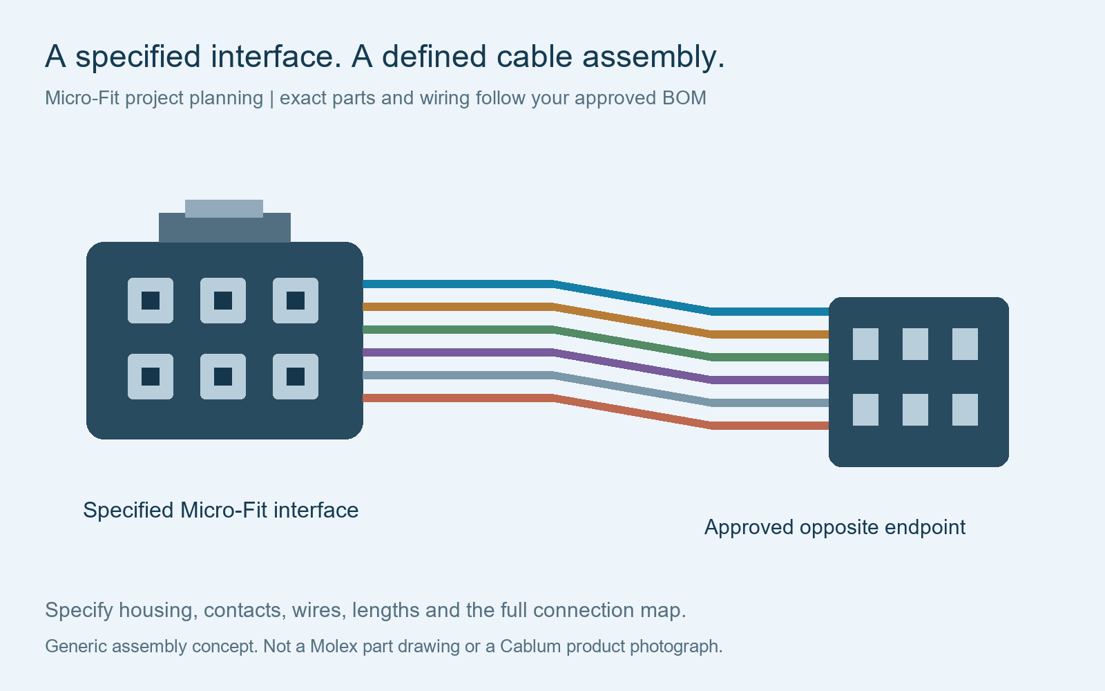
Define the finished connection
Micro-Fit to the endpoint your equipment design specifies
Connector-to-connector assembly
Specify both mating interfaces and the contact map. The opposite end can be reviewed against a different approved connector reference; straight-through wiring is not assumed.
Connector with individual leads
Define each wire’s gauge, color, free length, identifier and end treatment. List the exact terminal or ferrule reference where the lead connects to another device.
Branched assembly
Show the branch positions, destinations and covering requirements. Identify any splice separately and include the approved electrical and mechanical acceptance criteria.
These formats are starting points for drawing review, not a catalogue of stocked assemblies. For broader connector-to-wire configurations, see custom pigtail wire harness assemblies.
Component identification
Use full part numbers instead of a family name alone
Micro-Fit 3.0 identifies a connector family with 3.00 mm nominal contact pitch. Molex’s dual-row product specification identifies 43025 receptacle housings, 43020 plug housings, 43030 female crimp terminals and 43031 male crimp terminals. These are series references, not complete ordering codes.
The same specification distinguishes standard and TPA-related parts. Use the exact sales drawing, contact reference and mating information for the proposed combination. Do not transfer a standard-part requirement to another variant solely because it has the same family name.
| Item to identify | What the RFQ should include |
|---|---|
| Housing | Complete part number, position count, row layout, keying and retention requirements |
| Contacts | Complete terminal part number, approved wire range, insulation range and plating |
| Mating interface | Header or opposite housing reference and the required orientation |
| Wire and protection | Specified manufacturer references or controlled construction requirements |
Technical reference: Molex Micro-Fit dual-row product specification. The selected part documentation controls the actual configuration.
Wire, contact and tooling
Confirm the terminal before selecting the wire and crimp process
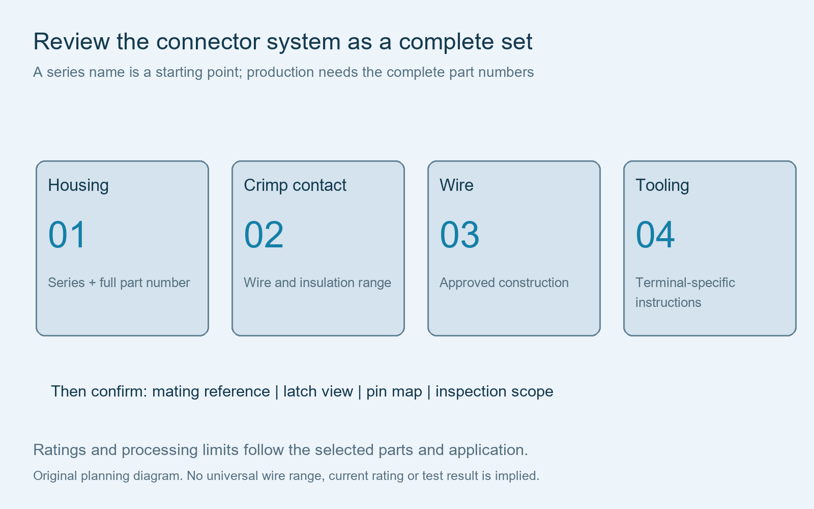
Request the application tooling specification for the exact crimp terminal. Review conductor size, insulation dimensions, strip preparation and applicable tooling instructions together. A contact that accepts one wire construction is not automatically suitable for another wire of the same nominal gauge.
Specify the operating current, voltage, ambient conditions and number of loaded circuits. The finished assembly rating must be evaluated against the selected connector, contact and wire combination. A headline connector-family rating is not a guaranteed rating for every custom harness.
If moving operation is required, provide routing, bend radius, travel and cycle requirements for review. The connector family name alone does not establish a flex-life result. See harness routing requirements.
Drawing controls
Show the latch view, contact positions and length references
Identify the mating-face and wire-entry views separately. Show the latch or other locating feature next to the pin map, and use that same reference on the assembly drawing. List every required connection and explicitly mark unused positions.
Dimension the finished assembly from named connector reference faces. Include free-wire dimensions, branch positions and tolerances where applicable. Define any local protection, labels and cable ties with their positions relative to the connector.
Use the manufacturer’s assembly guidance when placing restraints near the housing. Avoid substituting an arbitrary universal tie distance for the instructions that apply to the selected component and cable layout.
Related guides: pinout tables, connector orientation and length and dimension requirements.
Materials, inspection and quotation
Agree the component and acceptance requirements before production
State whether genuine Molex components are required and identify which parts, if any, may be considered for substitution. Proposed alternatives need review of the complete mating system, electrical requirements and processing instructions, followed by customer approval before use.
Specify the visual, dimensional and electrical checks required for the assembly. Where crimp-height, pull-force or cross-section verification is required, define the applicable terminal and wire combination, sampling, limits and records. Continuity and short-circuit coverage should follow the approved connection table. Additional tests and any IPC/WHMA-A-620 class are confirmed for the project.
Our component alternatives guide and test specification checklist explain the supporting inputs.
| Quotation input | Information to send |
|---|---|
| Controlled parts list | Housing, contact, mating part, wire and protection references |
| Assembly drawing | Pin map, views, lengths, tolerances, branches and identification |
| Operating requirements | Electrical loading, environment, routing and any movement requirements |
| Acceptance plan | Inspection coverage, test methods, limits and documentation |
| Order basis | Sample quantity, production quantity, packaging and destination |
Sample and production quantities, minimum material purchases, one-time tooling charges and lead times are reviewed against the project. A fixed minimum quantity or delivery promise should not replace a confirmed quotation. See wire harness quote breakdown.
Buyer questions
Micro-Fit 3.0 cable assembly questions
Is 43025 a complete cable assembly part number?
No. It is a housing series reference. The RFQ still needs the full housing code, contacts, wires, opposite endpoints and assembly drawing.
Can a Micro-Fit assembly use another connector at the opposite end?
Send both component references, the connection map and dimensions. The combination is reviewed against the approved design and processing requirements.
What wire gauge and current rating can be used?
These depend on the exact terminals, wires, loaded circuits and operating conditions. Provide the full part references and electrical requirements for review rather than selecting a universal family-wide value.
Can you quote a prototype or small batch?
Send the requested quantities. Component availability, material purchasing minimums, tooling and inspection scope determine the quotation basis and timing.
Can a photo replace a controlled drawing?
A photo or sample can help identify the interface. Confirm the component references, wiring, dimensions and acceptance requirements in controlled documentation before production.
Built to your approved specification
Send your Micro-Fit cable drawing and BOM
Share the selected housing and terminal references, mating information, connection table and quantities. Cablum reviews the custom wire harness requirements before confirming the materials, manufacturing scope, pricing and lead time.
Send Your Micro-Fit Cable RFQMolex and Micro-Fit names identify customer-specified components. This page describes Cablum’s custom assembly review.