Connector-to-connector layout
If both ends use connectors, identify each housing and terminal, the mating interface, cavity assignments and orientation. A connector appearance or pole count alone does not define the interface.
Built to your drawing · Custom wire harnesses
Cablum makes custom wire harnesses according to customer drawings, wire requirements and connector requirements. The finished assembly is defined by your design—not selected from a standard, ready-to-ship cable catalogue.
Use this page to define the physical assembly you need: its connection ends, wire paths, dimensions and protective details. Each proposed configuration requires drawing review before acceptance.
Define the finished assembly
The configurations below are ways to describe a requested design, not a catalogue of pre-approved products. Cablum must review the actual wires, connectors, terminations and assembly details for each project.
If both ends use connectors, identify each housing and terminal, the mating interface, cavity assignments and orientation. A connector appearance or pole count alone does not define the interface.
If one end remains outside a housing, specify the required end condition: stripped wire, tinned end or a named terminal. State the applicable preparation dimensions in the drawing. The termination method requires project review.
If the harness connects several points inside equipment, identify every branch destination, breakout location and end reference. Show how the harness relates to the available installation space.
Interface definition
| Product detail | What to define | Question to resolve |
|---|---|---|
| Connection ends | End identifiers, connector and terminal part numbers, mating references and orientation. | Are the specified ends compatible with the intended equipment interfaces? |
| Wire paths | Wire identification, specified wire type and size, and end-to-end cavity mapping. | Does each conductor have an unambiguous destination? |
| Unused positions | Identify unused cavities and any required plugs, seals or accessories by specification. | Is an empty cavity intentional, or is information missing? |
| Shield or drain termination | Where applicable, define the required shield construction and termination at each end. | Is the termination arrangement stated rather than left to assumption? |
| Component alternatives | State whether the specified part is mandatory or whether a proposed alternative may be reviewed. | Who must approve a change before it is used? |
For detailed part identification, use the connector selection requirements. A similar-looking component is not automatically an approved substitute.
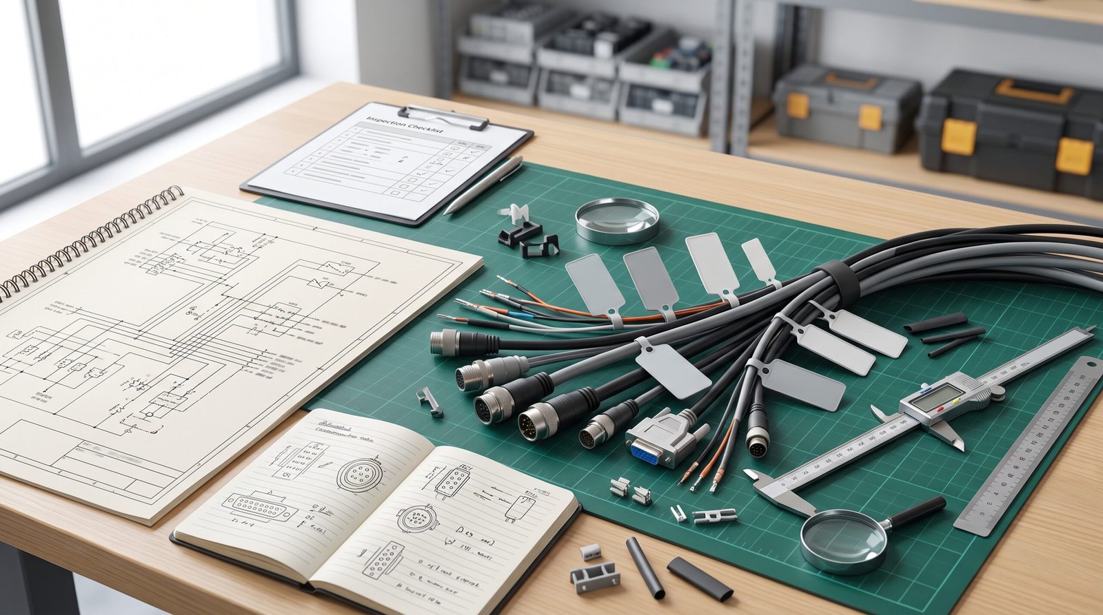
Fit and protection
Show where each measurement starts and ends—for example, a defined connector face or breakout point—and give the applicable tolerance. Overall length alone may not locate a branch.
Label each branch and show its exit direction. Clarify whether a drawing is a flattened layout or represents the installed routing.
Identify sleeve or other specified covering boundaries, exposed-wire sections and any required strain-relief features. Material and construction feasibility require review.
Define label text, position and reading direction. Flag nearby edges, moving parts or restricted access so these constraints can be considered against the proposed design.
See length and dimension requirements for measurement detail and routing requirements for installation inputs.
Illustrative specification format
This fictional example shows a documentation format only. It is not a completed customer project, a stock product or confirmation that the proposed construction has been accepted.
For a branched design, add an end reference and dimension set for every branch. The drawing checklist and BOM guide provide supporting detail.
Product questions
No. This page concerns custom wire harnesses made to customer drawings, wire requirements and connector requirements, rather than a fixed stock specification.
An illustration can explain an arrangement, but it does not establish part numbers, pin mapping, dimensions or ratings. Provide the technical definition for review before assuming the pictured construction can be supplied.
No. They describe possible request formats. Acceptance depends on review of the actual drawing, specified components and assembly requirements.
No. There is no single rating for every custom harness. Supply the intended requirements for evaluation against the chosen components and complete assembly design.
Start with your design
Share your drawing revision, wire and connector specifications, required quantity and unresolved design questions. Cablum will review the proposed assembly before confirming the scope.