Customer-specified power connections
Custom Flexible Power Cable Assemblies
Cablum cuts, prepares and assembles customer-specified power cable into finished connections to your approved drawing. Define the cable construction, both ends, core mapping and protective details for your equipment.
We also process harnesses for customer-defined high-current requirements. The actual cable, terminals, connectors and operating conditions are reviewed for each project; a cable diameter or jacket marking alone does not establish a finished-assembly current rating.
Request a Power Cable Assembly Quote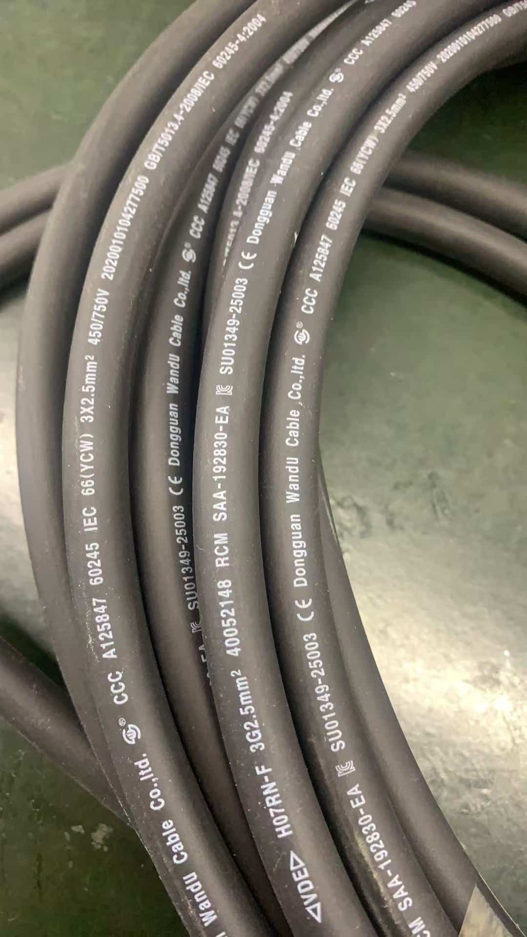
Actual cable material reference
From specified flexible cable to a drawing-defined assembly
The photographed cable carries H07RN-F, 3G2.5 mm² and 450/750 V markings. These are useful identification inputs for a quotation; supply the actual manufacturer’s datasheet, part reference and required supporting documents to confirm the selected material.
Cable identity
Specify the manufacturer, part number, cable type, core count and conductor cross-section. Include the outside diameter and tolerance where they affect a connector, gland or clamp.
Finished configuration
Show the overall length, jacket breakout at each end, individual core lengths and approved terminal or connector references. The bulk-cable marking does not define these details.
Component documentation
Request the material and compliance documents required by your project. Markings on the cable jacket do not automatically certify the finished cable assembly.
For terminology, LAPP’s H07RN-F 3G2.5 reference describes a flexible power/control cable with three 2.5 mm² cores including a protective conductor, and a 450/750 V cable rating. This is a reference for the designation, not evidence that the photographed cable is a LAPP product.
Multicore power lead construction
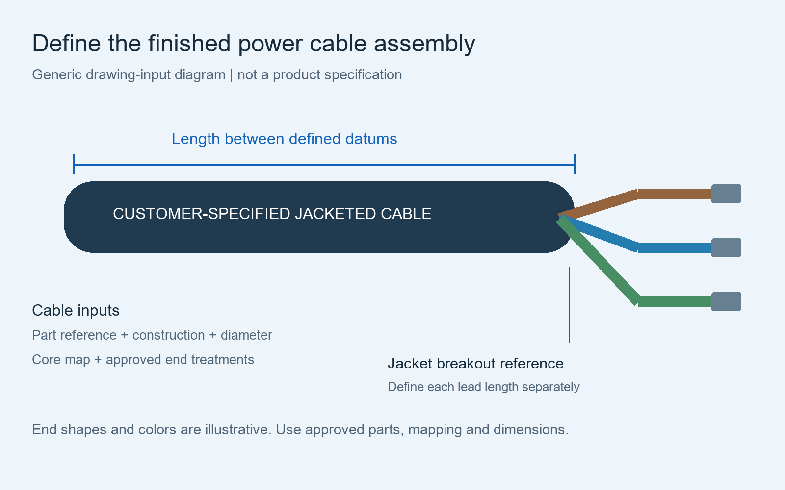
Define the jacket breakout and each prepared end
A jacketed power cable becomes an assembly when its ends and connections are controlled. Show where the jacket stops, where the cores separate and how each core reaches its specified interface.
Connector end
Identify the housing, contacts, accessories and core-to-cavity mapping. Check the specified wire and insulation fit against the selected contacts and the cable-entry range against the jacket diameter.
Terminal or prepared end
Name the terminal, lug or ferrule where required. If the interface requires a stripped conductor, give the approved preparation dimensions. Terminal geometry and conductor compatibility must be reviewed together.
Breakout protection
Show individual lead lengths, sleeves, heat-shrink boundaries, labels and strain-support components. Identify the measurement datum at the jacket exit and any areas that must stay exposed.
Use the length and dimension guide and pinout table guide for detailed documentation.
Customer-defined high-current requirements
Give the load conditions, not just the conductor size
“High current” is a project requirement rather than a rating assigned from a photograph. State the continuous load, any peak load and its duration, operating voltage, ambient conditions and installation arrangement.
Complete current path
Provide the selected cable, connector and terminal specifications for the complete path. Do not assign the cable’s permissible current to a contact or finished assembly without the applicable review.
Installation conditions
Identify the enclosure, grouping, route, supports and relevant heat sources. State whether the lead is fixed or subject to movement; flexible cable does not by itself prove continuous-motion suitability.
Required verification
If temperature-rise, voltage-drop, load or other validation is required, specify the method, configuration and acceptance criteria. Agree feasibility, responsibility and required records before ordering.
Assembly scope and inspection are confirmed for the project. This page does not offer a universal ampacity table or claim a load-testing capability that has not been agreed.
Quote-ready definition
What to send for a flexible power cable assembly quote
| Input | Information to provide | Assembly question it resolves |
|---|---|---|
| Cable specification | Approved part reference, datasheet, core count, cross-section and jacket diameter | Which material must be cut and prepared? |
| End interfaces | Connector, contact, terminal and accessory references for both ends | How does the assembly connect to the equipment? |
| Core mapping | Core identifiers and exact destination at each end, including protective-conductor treatment where present | Where does every core connect? |
| Dimensions | Overall length, datums, tolerances, jacket breakout and individual lead lengths | What physical arrangement must be built? |
| Protection and identification | Approved sleeves, end coverings, restraint parts and label details | Which visible details form part of the order? |
| Operating and acceptance inputs | Load conditions, installation constraints and agreed inspection or validation requirements | What needs review and how is conformity recorded? |
| Order and supply basis | Drawing revision, quantity, requested timing and customer-supplied or sourced component responsibility | What is included in the quotation? |
Keep specified parts aligned with the BOM. Any proposed cable or connector alternative needs customer approval before use.
Assembly acceptance
Inspect the finished lead against the approved definition
Agree inspection coverage and acceptance limits with the order. Relevant items can include cable identity, finished dimensions, jacket preparation, terminal or connector assembly, core mapping, protective-conductor connection where specified, and the defined electrical checks.
Continuity verification alone does not establish load capacity, temperature rise, environmental sealing or finished-product certification. Required additional tests and reports must be separately defined and confirmed.
See test specification requirements and customer-supplied component planning.
Flexible power cable assembly questions
Can Cablum process the power cable type shown in the photograph?
Yes. Cablum processes customer-specified power cable into custom harnesses and cable assemblies. Send the actual cable specification, drawing and end-component requirements so the proposed build can be reviewed.
Does the 3G2.5 marking mean a particular ampere rating?
It identifies the core arrangement and nominal conductor cross-section. The permissible load of the finished assembly depends on the selected cable and connection parts, operating conditions and installation; no universal ampere rating is assigned here.
Can I specify H07RN-F or another approved cable?
Provide the required manufacturer and part reference with the datasheet. If the material is customer supplied, agree its delivery and acceptance requirements. A substitute remains a proposal until approved.
Can the jacketed cable have different lead lengths at the ends?
Show each lead length from a stated jacket-breakout datum, with its core ID, termination and tolerance. Keep both end definitions clear in the drawing.
Is this the same as a battery lead or a high-voltage harness?
This page focuses on flexible jacketed power cable preparation and multicore breakouts. See battery cable assemblies for battery interface and polarity details, and high-voltage harnesses for that application scope.
Start with your specified cable
Send the cable specification and finished-assembly drawing
Include both end definitions, the core map, dimensions, component list, quantity and required acceptance records. Mark open current, interface or material questions for review before the assembly scope is confirmed.
Send Your Power Cable Drawing