Customer-specified equipment interfaces
Custom Panel-Mount Cable Assemblies
Connect an equipment-panel interface to the internal wiring your design requires. Cablum manufactures custom cable assemblies and wire harnesses to customer-approved drawings, specified wire and connector requirements.
Provide the panel-mount connector, internal endpoints, wiring map and finished dimensions. We review the complete assembly requirements before confirming component sourcing, processing and quotation scope.
Request a Panel-Mount Assembly Quote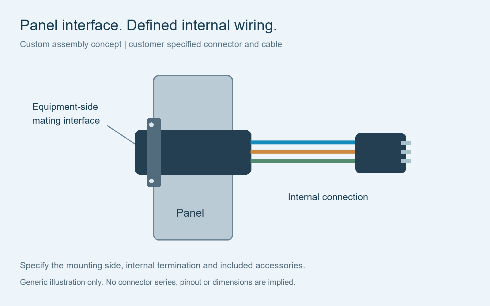
Define the finished assembly
A panel interface with a controlled internal connection
The panel connector and the wiring behind it need one coordinated specification. Identify the approved mounting arrangement, the contact connections and the internal termination rather than specifying only the visible equipment socket.
Panel connector to internal connector
Define both connector part numbers, the complete contact map, wire construction and the orientation of the internal cable exit.
Panel connector to individual leads
Specify each lead length, wire identifier and end preparation. State whether the equipment connection requires a terminal, ferrule or another approved treatment.
Panel connector to multiple endpoints
Identify each branch, its destination and the protection required inside the enclosure. Dimension the branch positions from named drawing references.
These are assembly formats for review against your components and drawing. For general connector-to-wire assemblies, see custom pigtail harnesses. For broader equipment wiring, see custom industrial cable assemblies.
Installation geometry
Specify the mounting side and space behind the panel
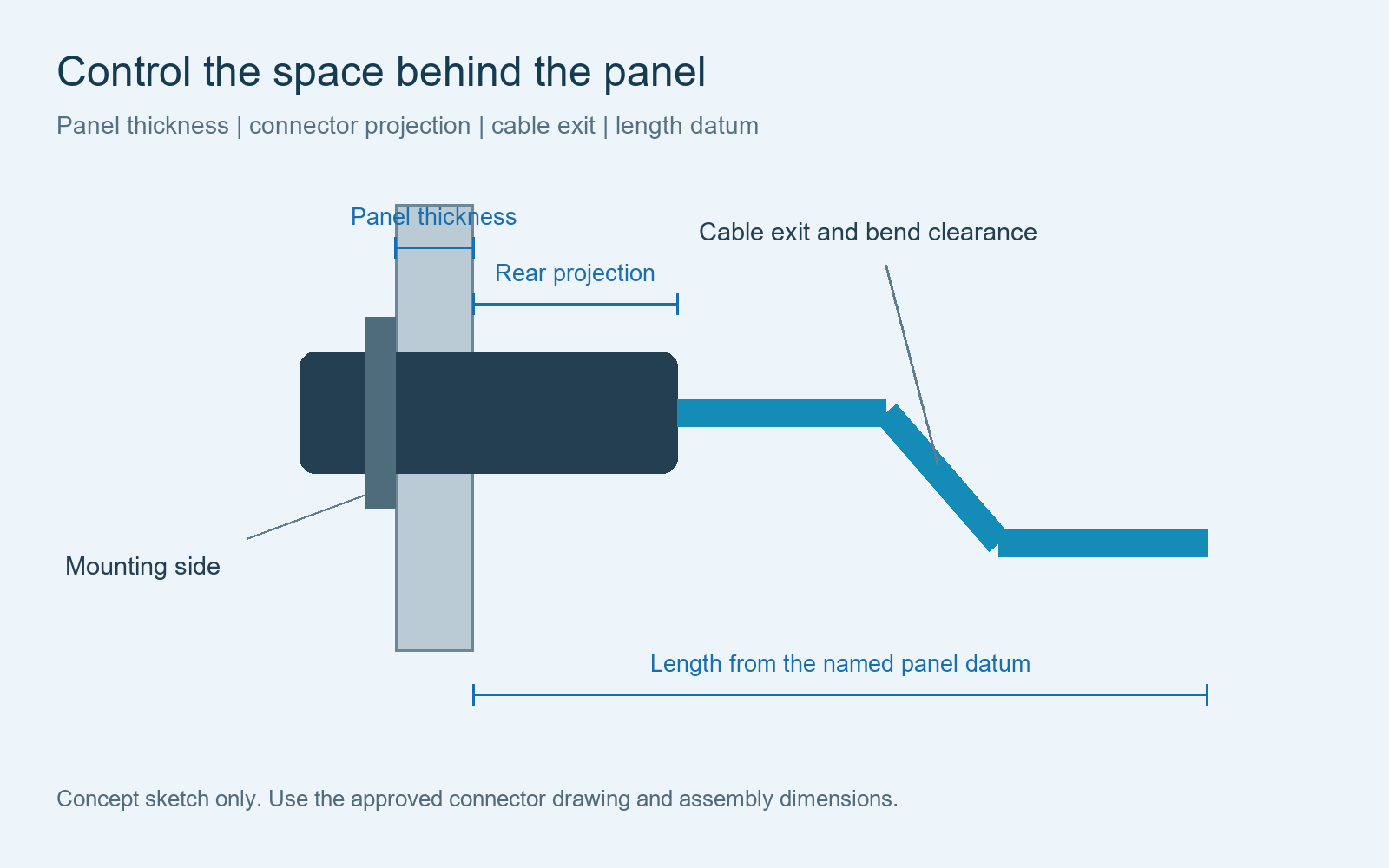
Provide the selected connector’s installation drawing and identify the side from which it is mounted. Include the panel thickness, cutout reference and the space available behind the mounted connector.
Mounting reference
Show the mounting face and the approved connector orientation. Use the exact part drawing to define cutout dimensions and any locating feature.
Rear clearance
Allow for the connector body, terminations, boot or backshell, and the specified cable exit. Include the cable manufacturer’s applicable bend constraints.
Length datum
State whether the harness length is measured from the panel face, connector reference face or another named point. Include a tolerance and the opposite-end datum.
Mounting requirements vary with the exact connector. For example, TE Connectivity’s Mini-Universal MATE-N-LOK application specification defines connector-specific panel thickness, cutout and insertion requirements. Apply the installation specification for your selected part rather than transferring those limits to another connector.
Related guides: length and dimension requirements and harness routing requirements.
Connection definition
Keep mounting orientation and pin numbering consistent
Identify the connector mating-face and wire-entry views separately. Show the key, notch or approved locating reference beside the pin map. The panel drawing should use the same orientation definition as the harness connection table.
Map each populated contact to its wire and destination. Define intentionally unused contacts and any shield-to-shell, chassis or grounding connection explicitly. Specify the wire and contact combination for each circuit.
A front-mounted and a rear-mounted connector should be treated as different part selections unless the approved component documentation establishes otherwise. Any proposed substitute needs review of the mating interface, mounting arrangement and connection definition.
See connector orientation requirements, the pinout table guide and component alternative approval.
Assembly boundary
List the mounting and protection items included in delivery
Mounting accessories
List any specified nut, washer, gasket, flange hardware or retaining item by part number. State whether it is fitted, supplied loose or provided by the equipment builder.
Cable protection
Define the approved boot, backshell, sleeving or local strain support. Describe its finished position and whether it must clear other enclosure components.
Supplied subassemblies
If the connector already includes factory leads, identify that supplied configuration and the operations requested on the remaining wire ends.
Identify panel fabrication and final enclosure installation as separate deliverables if they are part of your project. This quotation starts with the cable assembly and the specifically agreed accessories.
If environmental sealing is required, provide the selected component’s installation conditions and the finished-assembly acceptance requirements. Sealing performance is confirmed against the actual configuration and agreed verification scope.
Quotation package
What to include in a panel-mount cable assembly RFQ
| Input | What to provide | Purpose |
|---|---|---|
| Panel connector | Manufacturer part number, mating reference and installation drawing | Define the equipment interface and mounting arrangement |
| Panel context | Thickness, mounting side, cutout reference and rear clearance | Review the assembly envelope and cable exit |
| Wire and endpoints | Wire specifications, contacts, internal connectors or lead-end treatments | Define the materials and processing scope |
| Controlled drawing | Connection map, orientation, lengths, tolerances and branch positions | Establish the finished assembly definition |
| Delivery basis | Accessory list, sample and order quantities, packaging and destination | Prepare project-specific pricing and timing |
Include visual, dimensional and electrical acceptance criteria. Specify continuity, short-circuit and any required shield-connection checks with their coverage and record requirements. Mechanical fit checks require an agreed reference, such as the approved component drawing, sample panel or fixture.
Prices and lead times follow review of component availability and the confirmed assembly scope. See the drawing checklist and test specification requirements.
Buyer questions
Panel-mount cable assembly questions
Can a panel connector have a custom internal cable length?
Provide the connector and wire references, required endpoint and dimension datums. The configuration is reviewed against the parts and processing requirements before quotation.
What if the connector already has factory-attached wires?
Identify the factory subassembly and the work requested on its free ends. Specify any shortening, end preparation, identification and protection for review.
Are mounting nuts and seals included?
Include each required accessory in the BOM and identify whether it is fitted or supplied loose. The agreed assembly definition controls the delivery contents.
Does the cable quotation include an equipment panel?
The RFQ should distinguish the cable assembly from panel fabrication and enclosure installation. Confirm any additional deliverable separately during project review.
Can an alternative connector be proposed?
State which parts may be reviewed for substitution. Any alternative requires approval of its mating interface, mounting fit, circuit assignment and applicable requirements before use.
Built to your controlled specification
Send the panel interface and internal wiring requirements
Share your drawing, BOM, mounting reference, connection map and quantities. Cablum reviews the project information before confirming the custom cable assembly scope and quotation.
Send Your Panel-Mount Cable RFQ