OEM connector assembly guide
Magnetic Connector Cable Assemblies: RFQ & Pinout Guide
A magnetic interface needs a clear wire-termination definition as well as a mating connector. Specify the viewing direction, contact mapping, wire construction and opposite-end termination before releasing the assembly.
Cablum can solder and assemble magnetic connector wire harnesses to customer-approved drawings and component requirements, with continuity and short-circuit testing defined for the project. Send the connector specification, drawing, BOM and sample requirements for review.
Send Your Assembly Requirements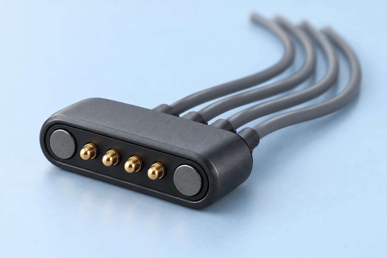
Assembly scope
Define both ends of the connection
A connector datasheet describes the component. The harness drawing must also define how each contact connects to a wire, where that wire ends and what the finished assembly must pass during inspection.
Magnetic interface
Identify the connector and mating half, contact arrangement, orientation features and required mating position. Reference the approved supplier drawing.
Individual leads
Specify conductor size and construction, insulation, wire IDs, finished length and whether the leads remain separate or form a protected bundle.
Opposite-end contacts
Define the contact part, termination method, material finish and required fit envelope. Mark proposed contacts as pending approval.
For broader build inputs, see the harness drawing checklist and BOM requirements.
Pinout control
Label the mating face and the termination face separately
State which side is shown beside each connector view. A view looking toward the solder tails can differ from a view looking at the mating contacts. Keep the physical contact identifiers consistent with the electrical connection table.
Use a visible datum
Show a key, locating feature or approved orientation reference. Include magnet polarity information only when it forms part of the controlled component or assembly definition.
Map every circuit
List each connector contact, wire identifier and destination. Identify intentionally unused contacts and circuits that must remain isolated.
Resolve ambiguous views
Clarify the drawing convention before assembly. A photograph can supplement a controlled view, but an unlabeled image does not define the pinout.
Use the connector orientation guide together with the pinout table guide.
Termination compatibility
Match fine wire to the selected contact and assembly method
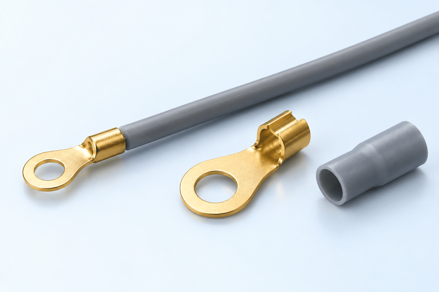
Check the wire size and construction against the contact’s documented wire range. A terminal that fits the equipment mechanically may still be unsuitable for the selected conductor.
Connector-side termination
Identify whether the contact provides a solder cup, solder tail or another wire termination. Use the selected part’s assembly instructions and define the required insulation and support.
Wire-to-terminal fit
Check conductor range, strand construction, insulation fit and relevant tooling. If the wire falls outside the documented range, resolve the selection before accepting the build.
Contact surface
Specify the contacting area, geometry and plating where these control the interface. Distinguish an approved part from a supplier-proposed alternative.
An unresolved compatibility issue belongs on the RFQ clarification list. Confirm the replacement contact, revised wire or approved connection method before releasing production requirements.
RFQ package
Six inputs to send with a magnetic connector harness drawing
| Input | What to define | Why it matters |
|---|---|---|
| Connector and mating half | Approved references, specification and supply responsibility | Establishes the interface and available termination features |
| Pinout views | Mating and wire-termination views, contact IDs and circuit mapping | Controls contact assignment and viewing direction |
| Wire construction | Gauge, stranding, insulation, identification and finished length | Supports termination and assembly review |
| Opposite-end contact | Part or proposed geometry, finish, fit envelope and approval status | Makes the complete connection reviewable |
| Assembly constraints | Protection, lead separation, strain support and permitted process | Clarifies the required physical build |
| Acceptance plan | Electrical checks, visual criteria, sample quantity and approval owner | Defines how the prototype and lot are accepted |
If the connector is customer supplied, include its revision, availability and incoming acceptance requirements. See customer-supplied component planning.
Approval sequence
Review the first article before the production lot
Agree the sample quantity and inspection record during quotation. Check the physical views and contact mapping against the released drawing, then record any approved changes before the lot is built.
Visual and dimensional
Define acceptable connector body condition, termination appearance, contact geometry, insulation coverage and measurement datums.
Electrical verification
State the required continuity and unintended-connection checks, their coverage and any additional project-specific tests.
Component versus assembly
Component current, voltage and mating-life ratings do not by themselves establish the completed harness rating. Use the project verification requirements for the assembly.
Align the sample review with sample feedback documentation and the test specification.
Magnetic connector cable assembly questions
Does the connector datasheet define the finished harness?
The datasheet describes the component. Add the wire construction, mapping, length, opposite-end termination, protection and inspection requirements to define the harness.
Can a connector be supplied by the customer?
Identify customer-supplied parts in the BOM and agree their specification, revision, delivery and acceptance requirements during project review.
What if the selected terminal does not cover the wire gauge?
Request an appropriate contact or an approved change to the wire or connection method. Record the disposition before the production build is released.
Can the mating view be used directly for wire soldering?
Use the view identified for wire termination by the controlled drawing. Clarify any difference between mating and termination views instead of assuming the same physical layout.
What can I send to Cablum for an initial review?
Send the connector specification, labeled views, connection table, wire requirements, opposite-end contact definition, quantities and test expectations. Mark any proposed components that still need approval.
Technical reference: Mill-Max wire termination and solder-cup applications. The instructions for the selected component govern its assembly requirements.
Project review
Make the complete magnetic connector assembly reviewable
Share the connector information and harness definition with Cablum. Identify open pinout, contact-fit and process questions so they can be resolved during project review.
Request an Assembly ReviewSoldered cable assemblies · Pigtail harness assemblies · Engineering & prototyping